
Solidified soil plant mixing treatment method and equipment thereof

A technology of processing equipment and processing methods, applied in the direction of roads, road repair, roads, etc., can solve the problems of uneven conveying volume, blockage of the feeding port, blockage of the feeding hopper, etc., to ensure the vibration effect, easy to break, and improve quality. Effect

Inactive Publication Date: 2020-08-28
镇江路机重工科技有限公司
View PDF8 Cites 2 Cited by
  • Summary
  • Abstract
  • Description
  • Claims
  • Application Information

AI Technical Summary

Problems solved by technology

The main raw material of solidified soil is soil or lime soil (lime soil refers to the product obtained after sedimentation and pressure filtration of waste mud water). During the preparation process, it is necessary to mix soil or lime soil with a small amount of cement and add a certain amount of soil curing agent. Therefore, when feeding soil or lime soil, due to its high viscosity, the soil cannot be fed in the feeding hopper, which will cause the blockage of the feeding hopper, which will affect the normal feeding. At present, the feeding hopper is used The way of setting the screw rod at the lower end is to assist the feeding of the soil. This feeding method is not effective, and the soil or lime will adhere to the screw rod, and the phenomenon of blocking the feeding port will still occur; Unevenness will lead to uneven delivery of the soil to the hopper, sometimes more and sometimes less, so that the weight of the soil cannot be accurately weighed, and the subsequent mixing of the soil with curing agent and cement will cause errors, and due to the viscosity of the soil It will be agglomerated, and the existing crushers are not effective in crushing soil, which will make soil clods with a diameter greater than 50mm be mixed into the original soil material, which will eventually affect the quality of the solidified soil

Method used


Image

  • Solidified soil plant mixing treatment method and equipment thereof
  • Solidified soil plant mixing treatment method and equipment thereof
  • Solidified soil plant mixing treatment method and equipment thereof

Examples


Embodiment Construction

[0034] In order to make the technical solution of the present invention clearer, the present invention will be further described below in conjunction with the accompanying drawings. Any solution obtained by equivalent replacement and conventional reasoning of the technical features of the technical solution of the present invention falls within the protection scope of the present invention. The fixed connection mentioned in the present invention and the fixed arrangement are common connection methods in the mechanical field, and welding, bolt and nut connection and screw connection are all available.

[0035] In describing the present invention, it is to be understood that the terms "upper", "lower", "front", "rear", "left", "right", "vertical", "horizontal", "top" , "bottom", "inner", "outer" and other indicated orientations or positional relationships are based on the orientations or positional relationships shown in the drawings, and are only for the convenience of describin...


PUM


Abstract

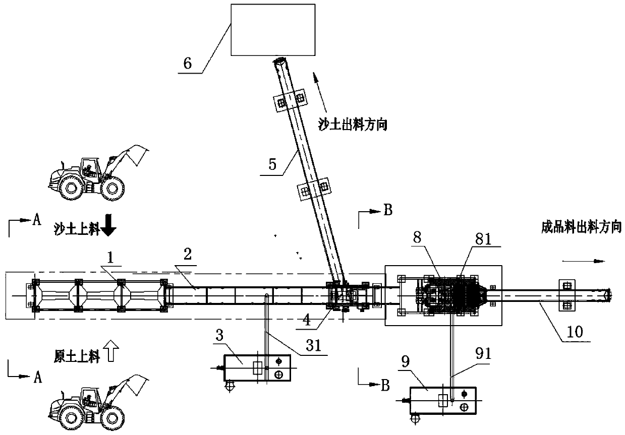
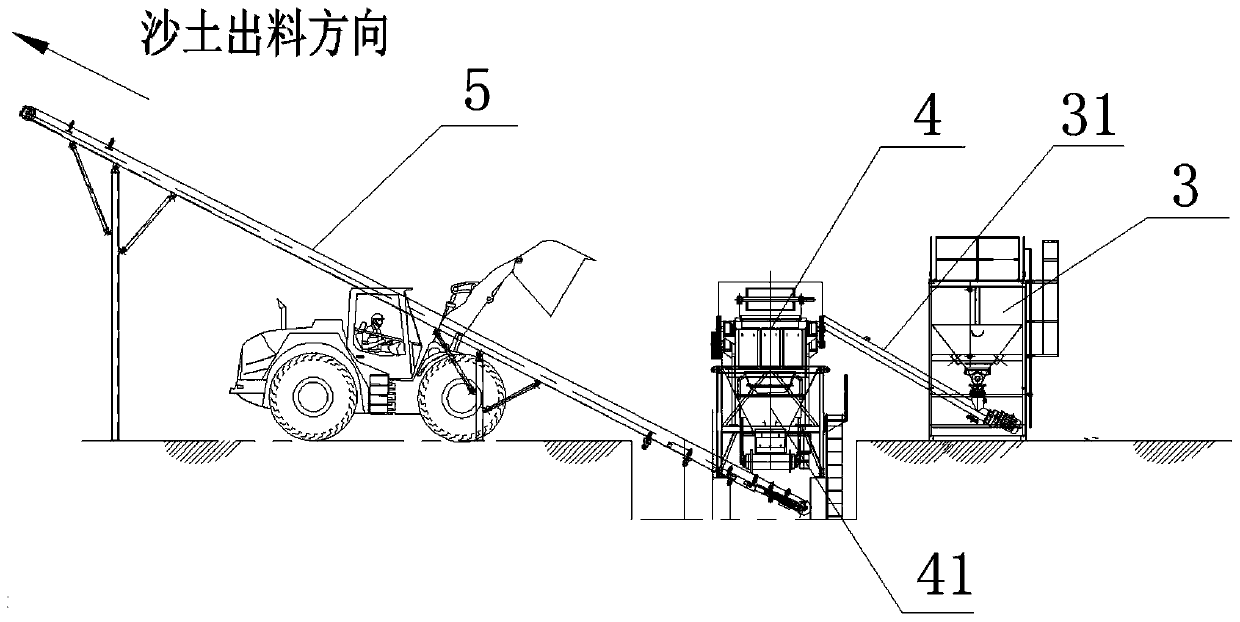
The invention relates to a solidified soil mixing method and equipment in highway construction and particularly relates to a solidified soil plant-mixing treatment method and equipment thereof. The method is characterized in that: raw soil is stored in a feeding hopper, after the raw soil is discharged in the feeding hopper, the raw soil is conveyed to a crusher through a first conveying belt, meanwhile, a lime powder bin conveys lime powder to the first conveying belt through a first spiral conveyor, the raw soil is covered with the lime powder, and the lime powder and the raw soil are conveyed into the crusher together; after the crusher performs preliminary crushing treatment and mixing on the mixture of the original soil and the lime powder, the crusher discharges the mixed sandy soilof the original soil and the lime powder to a second conveying belt through a distributor; and the second conveying belt conveys the mixed sandy soil to a soil covering field for soil covering treatment for 48 hours or longer, thus sanding original soil; and when the transport cart transports the sandy soil into the feeding hopper for discharging, the sandy soil is more uniform and smooth, and thesandy soil is easier to crush during crushing treatment.

Description

technical field [0001] The invention relates to a solidified soil mixing method and equipment in road construction, in particular to a solidified soil factory mixing treatment method and equipment thereof. Background technique [0002] With the continuous large-scale construction and maintenance of highways and urban roads in our country, natural sand and stone resources are increasingly scarce and exhausted, and environmental protection requirements in various places are constantly improving, and the production of machine-made sand is also strictly restricted, resulting in resource shortages for construction materials. dilemma. The shortage of raw materials has triggered a rise in the price of concrete products, further increasing construction costs, and further compressing construction profits. Relying on artificial synthetic materials to replace natural materials and solving the dilemma of basic materials is a major issue facing my country's construction industry. At pre...

Claims


Application Information

Patent Timeline
Patent Type & Authority Applications(China)
IPC IPC(8): E01C21/00
CPCE01C21/00
Inventor 朱剑铭邵文凯徐良全贡立新王红兵芦胜海张林孙杰升
Owner 镇江路机重工科技有限公司
Learn More