Inrush current suppression method applied to industrial frequency transformer in controllable inversion

A technology of power frequency transformer and magnetizing inrush current, applied in the field of security guarantee of distribution network automation system, can solve the problems of bias magnetization, inconvenient application, difficult to measure transformer remanence, etc. Effect

Inactive Publication Date: 2020-08-28
QINGDAO TOPSCOMM COMM
View PDF14 Cites 0 Cited by
  • Summary
  • Abstract
  • Description
  • Claims
  • Application Information

AI Technical Summary

Problems solved by technology

However, due to the inherent mechanical characteristics of the circuit breaker switch, there is often a delay in closing, which misses the best moment of closing and produces bias magnetism.
Moreover, the closing time of the phase selection closing technology is related to the residual magnetism in the magnetic core, but the residual magnetism in the transformer is difficult to measure, so there are still many inconveniences in the application

Method used


Image

  • Inrush current suppression method applied to industrial frequency transformer in controllable inversion
  • Inrush current suppression method applied to industrial frequency transformer in controllable inversion
  • Inrush current suppression method applied to industrial frequency transformer in controllable inversion

Examples


Embodiment Construction

[0029] In the following, the present invention will be further described in conjunction with the accompanying drawings and embodiments to specifically illustrate the technical solution of the present invention. The following embodiments are only used to illustrate the technical solutions of the present invention more clearly, and cannot be used to limit the protection scope of the present invention.

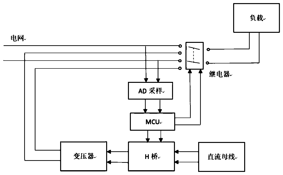
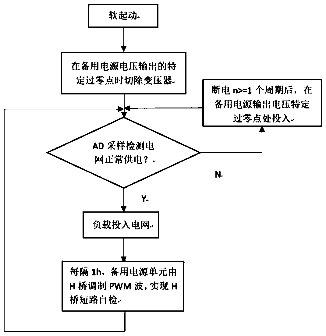
[0030] A method for suppressing the inrush current of a power frequency transformer in a controllable inverter. The application scenario diagram is as follows figure 1 As shown, the overall scheme design flow chart is as figure 2 As shown, the implementation steps of the scheme are described in detail below.

[0031] Step 1: Set a single-chip microcomputer to control the H-bridge circuit on the power supply side of the power frequency transformer to output power frequency voltage;

[0032] The PWM is controlled and modulated by the single-chip microcomputer to make the H-bridge circuit...


PUM


Abstract

The invention discloses an inrush current suppression method applied to an industrial frequency transformer in controllable inversion. The method comprises the following steps of: arranging a single chip microcomputer on the power supply side of an industrial frequency transformer to control an H-bridge circuit, so that an industrial frequency voltage can be output; carrying out soft starting; when the primary side voltage of the industrial frequency transformer is a specific zero crossing point, cutting off the transformer, recording and storing the direction of the zero crossing point, and when the transformer is switched on, obtaining the specific voltage zero crossing point; detecting the power supply state of a power grid based on an AD sampling unit, and executing corresponding actions according to the power supply state of the power grid; and when the power grid recovers power supply, putting the load into the power grid based on the AD sampling unit when it is judged that the power grid operates stably. According to the invention, the transformer is cut off and input through active control at the specific voltage zero crossing point, so that the residual magnetism changes towards the attenuation direction along the residual magnetism curve, and the inrush current when the transformer is input is obviously reduced; and the H-bridge circuit is controlled by the single-chip microcomputer to output the primary side voltage of the transformer, so that the operation is flexible, and the control precision is high.

Description

Technical field [0001] The invention relates to the field of safety assurance of a distribution network automation system, and in particular to a method for suppressing an excitation inrush current applied to a power frequency transformer in a controllable inverter. Background technique [0002] Terminal backup power: When the main station issues a test call instruction, the grid collection terminal must be able to ensure that the current meter reading data is uploaded. The terminal backup can continuously and stably supply power to the collection terminal when the power grid is out of power to ensure that it can continue to receive meter reading instructions and realize real-time upload of meter reading data. However, due to the hysteresis characteristics of the magnetic core material of the transformer, there is residual magnetism in the magnetic core, and the magnetic flux density in the magnetic core cannot change suddenly when the power frequency transformer is closed, causi...

Claims


Application Information

Patent Timeline
Patent Type & Authority Applications(China)
IPC IPC(8): H02H9/02H02J9/06
CPCH02H9/02H02J9/06
Inventor 李鸿儒徐鹏飞李健勋赵新举毕扬帆
Owner QINGDAO TOPSCOMM COMM
Why Eureka
Try Eureka