
Starting control method of inverter circuit comprising coupling transformer

A coupling transformer and inverter circuit technology, which is applied in the field of start-up control of inverter circuits, can solve the problems of coupling transformer excitation inrush current, reduction of magnetic core utilization rate, and increase in magnetic core volume, so as to reduce excitation inrush current and improve magnetic core performance. Utilization rate and effect of improving reliability

Active Publication Date: 2021-06-01
SHENZHEN YINGFEIYUAN TECH CO LTD
View PDF4 Cites 0 Cited by
  • Summary
  • Abstract
  • Description
  • Claims
  • Application Information

AI Technical Summary

Problems solved by technology

[0003] In the traditional half-bridge inverter circuit, a fixed switching frequency is generally used for soft start, but if a coupling transformer is added to the inverter circuit, and the traditional fixed switching frequency is used for soft start, the coupling transformer is easy to cause the Saturated by the double magnetic flux effect, the coupling transformer will generate an excitation inrush current, and even cause damage to the switching network connected to the coupling transformer in severe cases
[0004] The existing relatively simple solution is to design and reduce the working magnetic density of the transformer, but the disadvantage of this method is that it will reduce the utilization rate of the magnetic core, resulting in a larger volume of the magnetic core and higher cost

Method used


Image

  • Starting control method of inverter circuit comprising coupling transformer
  • Starting control method of inverter circuit comprising coupling transformer

Examples


Embodiment Construction

[0020] In order to make the objectives, technical solutions and advantages of the present invention more clear, the present invention will be described in further detail below in conjunction with the accompanying drawings and embodiments, wherein the same or similar symbols throughout represent the same or similar elements or have the same or similar functions element. It should be understood that the specific embodiments described here are only used to explain the present invention, not to limit the present invention.

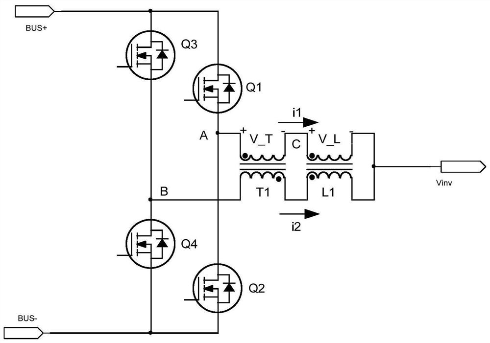
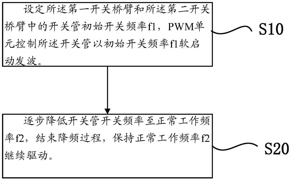
[0021] see figure 1 as well as figure 2 , figure 1 A schematic diagram of the circuit structure of the inverter circuit provided by the embodiment of the present invention, figure 2 It is a schematic flow chart of the start-up control method of the inverter circuit provided by the embodiment of the present invention.

[0022] Such as figure 1 As shown, the present invention provides an inverter circuit containing a coupling transformer. The inverter cir...


PUM


Abstract

The invention provides a starting control method of an inverter circuit comprising a coupling transformer, the inverter circuit comprises a positive bus, a negative bus, a first switch bridge arm, a second switch bridge arm, a coupling transformer and a coupling inductor, the starting method comprises the following steps: setting an initial switching frequency f1 of a switching tube in the first switch bridge arm and the second switch bridge arm; carrying out soft start wave sending at an initial switching frequency f1, gradually reducing the switching frequency to a normal working frequency f2, ending a frequency reduction process, keeping the normal working frequency f2 to continue driving, and taking a high switching frequency as a switching tube starting frequency, so that the time acting on the transformer is shortened, the smaller the magnetic density generated in a magnetic core of the coupling transformer is, and the magnetic core is not easy to saturate; the excitation inrush current generated when the inverter circuit comprising the coupling transformer is started can be remarkably reduced, so that the reliability of the inverter circuit is improved, the magnetic core utilization rate of the transformer can be effectively improved, and the size and the cost of the inverter circuit are reduced.

Description

technical field [0001] The invention belongs to the technical field of power electronic power supplies, and relates to a start-up control method of an inverter circuit, in particular to a start-up control method of an inverter circuit including a coupling transformer. Background technique [0002] The inverter circuit (Inverter Circuit) corresponds to the rectifier circuit (Rectifier Circuit), which is designed to convert direct current into alternating current. In recent years, inverter circuits have been widely used in industry, among which the application of half-bridge inverter circuits in DC to AC power supplies is the most prominent. [0003] In the traditional half-bridge inverter circuit, a fixed switching frequency is generally used for soft start, but if a coupling transformer is added to the inverter circuit, and the traditional fixed switching frequency is used for soft start, the coupling transformer is easy to cause the Due to the double magnetic flux effect a...

Claims


Application Information

Patent Timeline
Patent Type & Authority Applications(China)
IPC IPC(8): H02M7/5387H02M1/08H02M1/36H02M1/32
CPCH02M7/5387H02M1/08H02M1/36H02M1/32Y02B70/10
Inventor 胡小明崔彬余仕君肖旭潘
Owner SHENZHEN YINGFEIYUAN TECH CO LTD
Learn More