Positioning method and system for in-situ visualization of biological targets

A positioning method and biological technology, applied in image analysis, medical science, analysis using fluorescence emission, etc., can solve the problems of inability to display or mark biological targets, achieve shortened positioning time, simple operation equipment, and improve positioning efficiency Effect

Active Publication Date: 2021-12-21
北京瀚丞医用设备有限公司
View PDF16 Cites 0 Cited by
  • Summary
  • Abstract
  • Description
  • Claims
  • Application Information

AI Technical Summary

Problems solved by technology

[0011] In order to solve the above-mentioned problem that the biological target cannot be displayed or marked on the living body in situ so as to accurately identify the position, shape and boundary of the biological target, the first aspect of the present invention provides a biological target in situ display using optical projection technology. Visible positioning method, which can accurately realize optical in situ positioning of biological targets and their boundaries

Method used


Image

  • Positioning method and system for in-situ visualization of biological targets
  • Positioning method and system for in-situ visualization of biological targets
  • Positioning method and system for in-situ visualization of biological targets

Examples


Embodiment 1

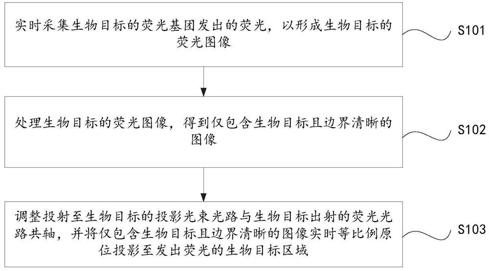
[0085] figure 1 A flow chart of a positioning method for in-situ visualization of a biological target in this embodiment is given. Such as figure 1 As shown, the in-situ visible positioning method of the biological target in this embodiment includes:

[0086] S101: Collect the fluorescence emitted by the fluorophore of the biological target in real time to form a fluorescent image of the biological target.

[0087] In step S101, the fluorophore of the biological target is an intrinsic fluorophore of the biological target or an exogenous fluorophore received by the biological target.

[0088] When the fluorescent group of the biological target is the inherent fluorescent group of the biological target, the fluorescence emitted by the fluorescent group of the biological target is: the fluorescence formed spontaneously by the inherent fluorescent group of the biological target or the inherent fluorescent group of the biological target by an external light source Fluorescence p...

Embodiment 2

[0132] Figure 4 A schematic diagram of the principles of a positioning system for in-situ visualization of biological targets in this embodiment is given.

[0133] The positioning system for in-situ visualization of biological targets in this embodiment includes an imaging system, an image processing and analysis unit, an image positioning and projection unit, and a beam splitter.

[0134] This embodiment provides a positioning system for in-situ visualization of biological targets, including:

[0135] (1) An imaging system, which is used to collect the fluorescence emitted by the fluorescent group of the biological target in real time, so as to form a fluorescent image of the biological target.

[0136] The fluorophore of the biological target is the intrinsic fluorophore of the biological target or the exogenous fluorophore received by the biological target.

[0137] When the fluorescent group of the biological target is the inherent fluorescent group of the biological ta...

Embodiment 3

[0177] Such as Image 6 As shown, the in-situ visible positioning system for biological targets in this embodiment includes an imaging system, an image positioning and projection unit, an image processing and analysis unit, an excitation light source, a supplementary light source and a spectroscope. Moreover, the imaging system, image positioning and projection unit, image processing and analysis unit and a spectroscope are integrated into a core whole to form a complete positioning device. The imaging system, image positioning and projection unit, image processing and analysis unit and a beam splitter are all arranged inside the positioning device. The positioning device is also provided with a window for the transmission of the fluorescent light and the projection beam.

[0178] In this embodiment, the optical path from the biological target to the lens in the image positioning projection unit is set as the first optical path, the optical path from the biological target to ...


PUM


Abstract

The invention belongs to the field of biological target positioning. In order to solve the problems that the boundaries of biological targets cannot be accurately identified and the biological targets cannot be marked in situ, a positioning method and system for in-situ visual positioning of biological targets are provided, which can It can accurately locate, identify, protect and determine the boundary of biological targets in real time and efficiently. Among them, the in-situ visual positioning method of biological targets includes collecting the fluorescence emitted by the fluorescent groups of biological targets in real time to form a fluorescent image of biological targets; processing the fluorescent images of biological targets to obtain images containing only biological targets and clear boundaries ; Adjust the optical path of the projection beam projected to the biological target to be coaxial with the fluorescent optical path emitted by the biological target, and project the image containing only the biological target and with clear boundaries in real time and in situ in equal proportions to the biological target area emitting fluorescence.

Description

technical field [0001] The invention belongs to the field of high-end medical optical instruments, and in particular relates to a positioning method and system for in-situ visualization of biological targets. Background technique [0002] The statements in this section merely provide background information related to the present invention and do not necessarily constitute prior art. [0003] In the field of biomedicine, some normal or diseased biological targets (such as tumors, microorganisms, lymph nodes, soft tissue sarcomas, or other tissues or organs) are integrated with the surrounding environment, and professionals cannot accurately determine the location of biological targets, even if they judge Knowing its location, it is also difficult to judge its complete shape and precise boundary. This creates difficulties for the later operations of biological targets (such as in situ protection, in situ removal, surgical resection or puncture, etc.), and it is impossible to ...

Claims


Application Information

Patent Timeline
Patent Type & Authority Patents(China)
IPC IPC(8): A61B5/00G06T7/00G06T7/11G06T7/136
CPCA61B5/0071A61B5/0033G06T7/0012G06T7/11G06T7/136G06T2207/10064G06T2207/30096G06T2207/20024
Inventor 王子兰
Owner 北京瀚丞医用设备有限公司
Why Eureka
Try Eureka