Bilateral rotary laser-TIG electric arc welding method and clamping tool for cross joint

A welding method, cross-shaped technology, applied in laser welding equipment, welding equipment, manufacturing tools, etc., can solve problems such as undercut, affecting product mechanical properties, stress concentration, etc., to increase melting area and increase penetration efficiency , to avoid the effect of stress concentration

Active Publication Date: 2020-09-01
NORTH CHINA UNIV OF WATER RESOURCES & ELECTRIC POWER
View PDF17 Cites 0 Cited by
  • Summary
  • Abstract
  • Description
  • Claims
  • Application Information

AI Technical Summary

Problems solved by technology

However, this method is prone to defects such as undercut and undercut in the upper fillet weld, and a weld formed by excessive liquid metal protruding from the bottom of the fillet weld, which can easily cause stress concentration and affect the mechanical properties of the product.

Method used


Image

  • Bilateral rotary laser-TIG electric arc welding method and clamping tool for cross joint
  • Bilateral rotary laser-TIG electric arc welding method and clamping tool for cross joint
  • Bilateral rotary laser-TIG electric arc welding method and clamping tool for cross joint

Examples


Embodiment Construction

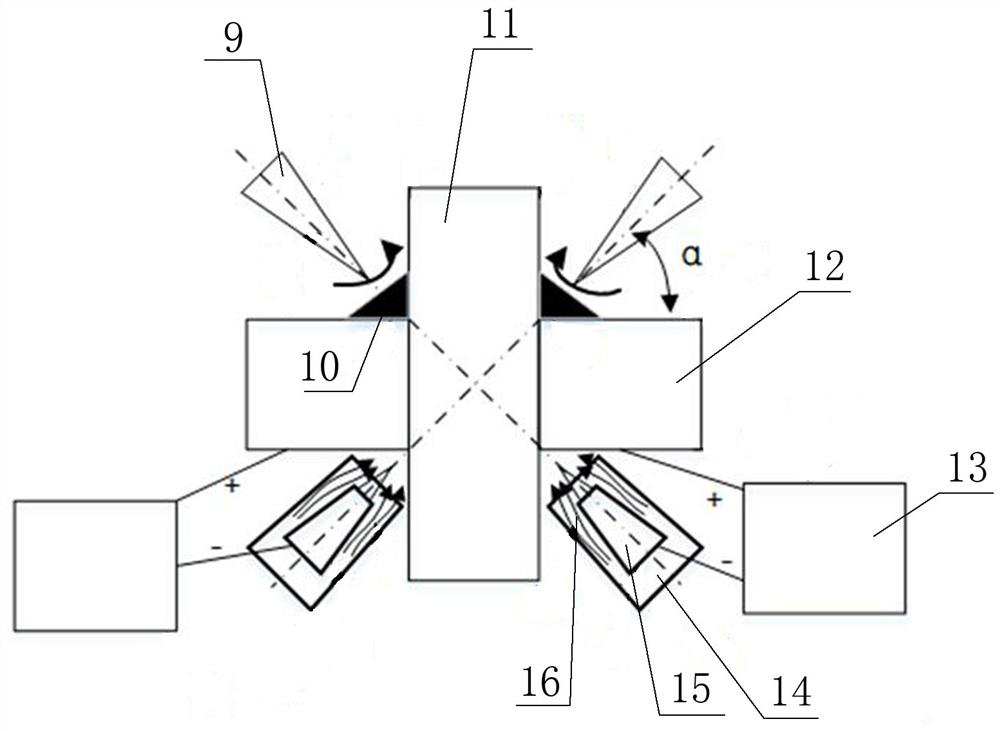
[0034] Such as figure 1 As shown, a double-sided rotating laser-TIG arc welding method of a cross-shaped joint of the present invention consists of two laser emitting heads arranged on both sides of the upper part of the cross-shaped joint and two TIG welding heads arranged on both sides of the lower part of the cross-shaped joint Welding torch 15 cooperates to weld the cross joint. The included angle α between the axis of the laser emitting head and the horizontal plane is 30-80°. The laser emitting head and the TIG welding torch 15 each rotate with a certain radius with a center line parallel to its own axis, and the laser emitting head and the TIG welding torch 15 at the diagonal position remain coaxial. Before welding, the metal powder 10 matched with the laser beam 9 emitted by the laser emitting head is preset on both sides of the upper part of the cross-shaped joint. Liquid metal lifts. The TIG welding gun 15 is coaxially distributed in the shielding gas nozzle 14 , ...


PUM

PropertyMeasurementUnit
melting pointaaaaaaaaaa

Abstract

The invention relates to the technical field of laser welding, in particular to a bilateral rotary laser-TIG electric arc welding method and clamping tool for a cross joint. The bilateral rotary laser-TIG electric arc welding method for the cross joint is characterized in that two laser emitting heads arranged on the two sides of the upper part of the cross joint and two TIG welding guns arrangedon the two sides of the lower part of the cross joint are matched to weld the cross joint, each laser emitting head and each TIG welding gun rotate around the center lines parallel to the axes of thelaser emitting head and the TIG welding gun, and the laser emitting heads and the TIG welding guns located at the diagonal positions keep coaxial; and before welding, metal powder matched with laser beams emitted by the laser emitting heads is arranged on the two sides of the upper part of the cross joint in advance, and molten pool liquid metal is lifted through shielding gas nozzles located on the two sides of the lower part of the cross welding joint in the welding process. According to the bilateral rotary laser-TIG electric arc welding method for the cross joint, the problems of fillet weld collapse and undercut defects at the upper part of the crisscross joint, stress concentration caused by fillet weld bulges at the lower part of the crisscross joint and incomplete fusion of a jointsurface can be solved.

Description

technical field [0001] The invention relates to the technical field of laser welding, in particular to a welding method and a clamping tool for double-sided rotating laser-TIG arcs of a cross-shaped joint. Background technique [0002] Compared with traditional welding methods, laser welding technology has many advantages such as small welding deformation, deep weld penetration depth and high welding efficiency, so it has been widely used in aerospace, automobile, shipbuilding and other manufacturing fields. [0003] With the development of my country's industry, unconventional joints, such as cross joints, are required in some fields. At present, it is generally used for cross-shaped joints to use laser beams to weld on one side and then weld on the other side. This method not only has low welding efficiency, but also tends to cause unfused joints. Filler metal tends to appear in the upper fillet weld and undercut defects, and the lower fillet weld bulges to cause stress c...

Claims


Application Information

Patent Timeline
Patent Type & Authority Applications(China)
IPC IPC(8): B23K26/348B23K26/60B23K26/14B23K26/08
CPCB23K26/0869B23K26/14B23K26/348B23K26/60
Inventor 彭进许红巧
Owner NORTH CHINA UNIV OF WATER RESOURCES & ELECTRIC POWER
Why Eureka
Try Eureka