Undisturbed switching control method of magnetic suspension energy storage flywheel charging and discharging control system

A charge and discharge control, energy storage flywheel technology, applied in the direction of AC network load balancing, etc., can solve problems such as malfunction, prolong voltage rise time, large current, etc., reduce voltage and current fluctuations, and improve charge and discharge switching speed. , to avoid the effect of current impact

Active Publication Date: 2020-09-01
华驰动能(北京)科技有限公司
View PDF1 Cites 4 Cited by
  • Summary
  • Abstract
  • Description
  • Claims
  • Application Information

AI Technical Summary

Problems solved by technology

When using the traditional method, only when the voltage U dc fall to U disc Below, the flywheel starts to discharge and gradually raises the voltage to V ref , the large DC bus support capacitor not only cannot stabilize the voltage, but prolongs the voltage rise time, which is generally in milliseconds or even tens of milliseconds. The sex

Method used


Image

  • Undisturbed switching control method of magnetic suspension energy storage flywheel charging and discharging control system
  • Undisturbed switching control method of magnetic suspension energy storage flywheel charging and discharging control system
  • Undisturbed switching control method of magnetic suspension energy storage flywheel charging and discharging control system

Examples


Embodiment Construction

[0024] In order to understand the characteristics and technical content of the present invention in more detail, the technical solutions in the examples of the present invention will be clearly and completely explained below in combination with the accompanying drawings in the examples of the present invention, taking the permanent magnet synchronous motor as an example. The accompanying drawings are for reference and description only, and are not intended to limit the examples of the present disclosure.

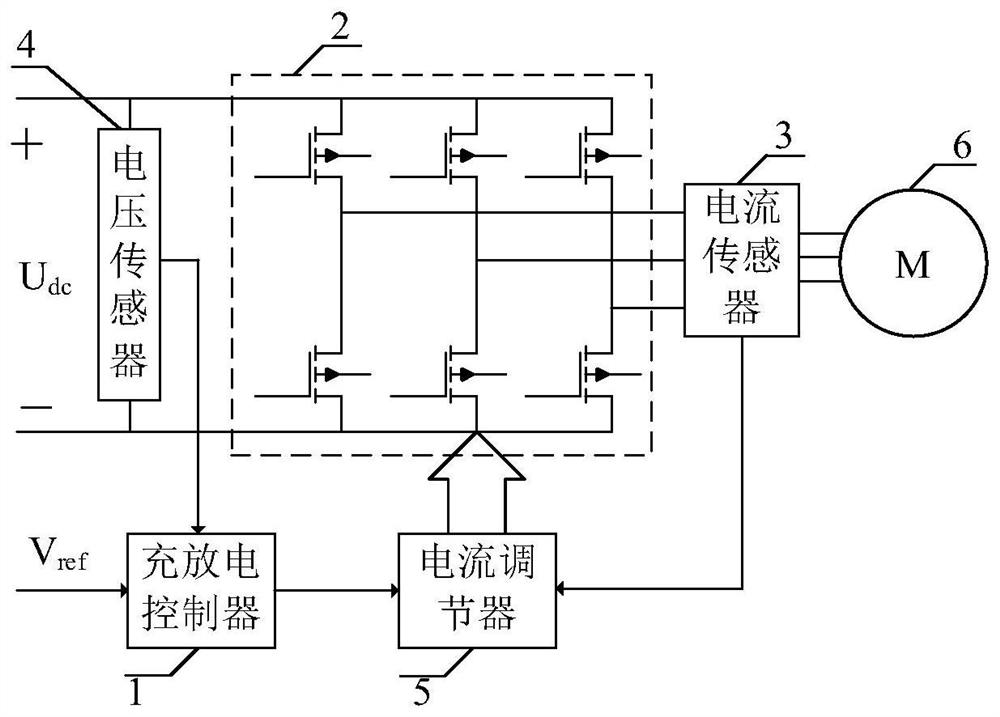
[0025] like figure 1 As shown, the necessary topological diagram of the charging and discharging control system of the maglev flywheel provided by the invention, the control system includes a charging and discharging controller 1, a three-phase bridge 2, a current sensor 3, a voltage sensor 4, a current regulator 5, and a flywheel 6. The charge-discharge controller 1 inputs the stabilized voltage value V through the flywheel 6 ref and the DC bus voltage U collected by the v...


PUM


Abstract

The invention discloses an undisturbed switching control method of a magnetic suspension energy storage flywheel charging and discharging control system, which is used for energy storage flywheel charging and discharging switching control, guarantees that the voltage is stable and free of pulsation in the charging and discharging process, and achieves the switching time of 0. According to the method, voltage outer loop and current inner loop control is adopted in the charging process, the discharging process and the charging and discharging switching process, when the direct-current bus voltage Udc is greater than a voltage stabilization value Vref set by a flywheel, the output of a voltage outer loop proportional integral link is positive, a three-phase bridge works in an inversion state,the flywheel accelerates charging, and conversion from electric energy to kinetic energy is achieved; when the direct-current bus voltage Udc is less than the flywheel voltage stabilization value Vref due to mains supply power failure or power insufficiency, the output of the voltage outer loop proportional integral link is negative, the three-phase bridge works in a controllable rectification state, and conversion from mechanical energy to electric energy is achieved. Because the whole process of the voltage outer loop is controlled in real time, the method essentially solves the problem ofcurrent and voltage fluctuation during charging and discharging switching of the energy storage flywheel, and improves the dynamic response speed and power supply quality of the flywheel battery.

Description

technical field [0001] The invention relates to the field of charge and discharge of an energy storage flywheel, in particular to a non-disturbance switching control method for a charge and discharge control system of a magnetic levitation energy storage flywheel. Background technique [0002] Compared with traditional chemical batteries, the energy storage flywheel has the characteristics of long service life, low maintenance cost, high charge and discharge power, and no environmental pollution. The energy storage flywheel can reach tens of millions of deep charge and discharge, which is an advanced physical energy storage Way. In particular, its long charge and discharge life and high power density are especially suitable for occasions that require frequent and rapid charge and discharge, such as power frequency modulation batteries, rail transit braking energy recovery, and dynamic power preservation UPS. With the increasing demand for energy storage in my country, the d...

Claims


Application Information

Patent Timeline
IPC IPC(8): H02J3/30
CPCH02J3/30Y02E60/16
Inventor 苏森王志强
Owner 华驰动能(北京)科技有限公司
Why Eureka
Try Eureka