Rotary drum type solid-liquid separator

A solid-liquid separator and drum-type technology, which is applied in the direction of filtration separation, separation methods, chemical instruments and methods, etc., can solve the problems of inability to form variable volume, cannot satisfy high-pressure deep dehydration, etc., and achieve improved pressing effect and movement resistance small effect

Active Publication Date: 2020-09-04
嘉兴绿方舟环保技术有限公司
View PDF5 Cites 2 Cited by
  • Summary
  • Abstract
  • Description
  • Claims
  • Application Information

AI Technical Summary

Problems solved by technology

However, since the filter screen of this invention is fixed on the same rotating component, it cannot form variable volume forced dehydration, so this device can only be applied under the condition of high water content of concentrated filtration, and cannot meet high pressure Requirements for deep dehydration

Method used


Image

  • Rotary drum type solid-liquid separator
  • Rotary drum type solid-liquid separator
  • Rotary drum type solid-liquid separator

Examples


Embodiment 1

[0025] Embodiment one, be used for the sludge dewatering of piling construction site:

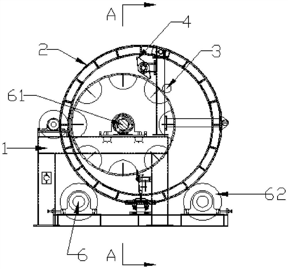
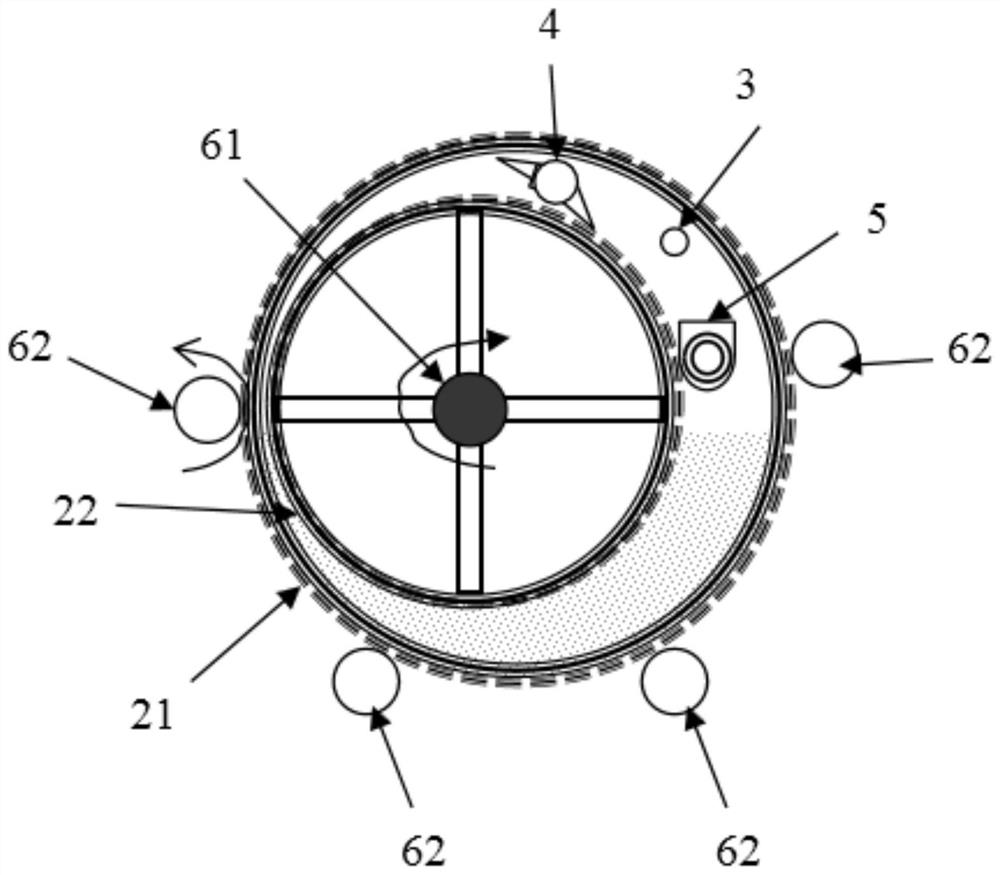
[0026] refer to image 3 , Figure 4 , a drum type solid-liquid separator of the present invention includes a frame 1, a drum group 2, a feeding mechanism 3, a discharging mechanism 4, a discharging mechanism 5 and a driving mechanism 6, and the drum group 2 includes a diameter The inner drum 22 and the outer drum 21 are different and set in order from the inside to the outside. Both the inner drum 22 and the outer drum 21 can permeate the liquid. The inner drum 22 and the outer drum 21 can be rotatably fixed on the machine respectively. On the frame 1 and rotate around different centers of circles to form a gradually shrinking horn-shaped channel to form a dehydration zone with gradually increasing pressure. A feeding mechanism 3, a discharging mechanism 4 and a discharging mechanism 5 are arranged in the horn-shaped channel.

[0027] Outer drum 21 adopts 25MM thick A3 steel plate of D25...

Embodiment 2

[0033] Embodiment two, be used for river sludge dewatering:

[0034] refer to Figure 5 , Figure 6 , a drum type solid-liquid separator of the present invention includes a frame 1, a drum group 2, a feeding mechanism 3, a discharging mechanism 4, a discharging mechanism 5 and a driving mechanism 6, and the drum group 2 includes a diameter The inner drum 22, the middle drum 23 and the outer drum 21 are set differently from the inside to the outside in order. The inner drum 22 and the outer drum 21 are both for liquid diafiltration, and the middle drum 23 is not for liquid diafiltration. The inner drum 22. The intermediate drum 23 and the outer drum 21 are respectively rotatably fixed on the frame 1 and rotate around different centers of circles. A gradually shrinking horn-shaped channel is formed between adjacent drums to form a dehydration zone with a gradually increasing pressure. A number of feeding mechanisms 3 , discharging mechanisms 4 and discharging mechanisms 5 are ...


PUM

PropertyMeasurementUnit
widthaaaaaaaaaa
porosityaaaaaaaaaa

Abstract

The invention discloses a rotary drum type solid-liquid separator which comprises a rack, a rotary drum set, a feeding mechanism, an unloading mechanism, a discharging mechanism and a driving mechanism. The rotary drum set comprises at least two rotary drums which are different in diameter and sequentially arranged in a sleeving mode from inside to outside. At least one of the two adjacent rotarydrums is used for filtering liquid, the plurality of rotary drums can rotate respectively, every two adjacent rotary drums rotate around different circle centers to form a gradually-contracted ox horn-shaped channel, and therefore a liquid removal interval with the pressure intensity gradually increased is formed. At least one of the rotary drums is fixed on the rack. At least one feeding mechanism and at least one unloading mechanism are arranged in each ox horn-shaped channel. The number of the discharging mechanism and the number of the driving mechanism in the whole rotary drum type solid-liquid separator are respectively at least one. The rotating directions of the rotary drums are consistent. Forced pressure filtration and variable-volume filtration can be conducted at the same time,and the solid content of filter cakes can be conveniently adjusted.

Description

【Technical field】 [0001] The invention relates to the technical field of solid-liquid separators, in particular to the technical field of drum-type solid-liquid separators. 【Background technique】 [0002] Drum type dehydrator is a kind of filtration equipment widely used in the field of solid-liquid separation, including drum filter, vacuum drum filter and centrifugal drum filter. The drum filter has the advantages of compact equipment, good operating environment and no need for manual intervention, but at the same time, this type of dehydration filter equipment also generally has the problems of low filtration pressure and high moisture content of the filter cake. [0003] In order to increase the dehydration pressure of the drum, the Chinese patent application number 201710341223.8 discloses an involute drum eccentric extrusion filter press. The involute drum eccentric extrusion filter press can feed the slurry under pressure, vacuum suction, and mechanical extrusion. un...

Claims


Application Information

Patent Timeline
Patent Type & Authority Applications(China)
IPC IPC(8): B01D25/12
CPCB01D25/12
Inventor 唐志超朱忆人潘政尧徐诗铭徐丽娟张晓燕
Owner 嘉兴绿方舟环保技术有限公司
Why Eureka
Try Eureka