
Slewing bearing worm wheel outer gear ring processing method and rotary driving device

A technology of slewing bearing and processing method, applied in the direction of gear transmission, transmission, transmission parts, etc., can solve the problems of slewing drive damage, peeling, high cost of copper alloy materials, and achieve the effect of improving bearing capacity

Inactive Publication Date: 2020-09-04
MAANSHAN JINGYI ENG MACHINERY
View PDF5 Cites 1 Cited by
  • Summary
  • Abstract
  • Description
  • Claims
  • Application Information

AI Technical Summary

Problems solved by technology

The material of the worm gear in the worm gear transmission is generally 50Mn or 42CrMo, which is prone to glue when meshing with the above worm, which will cause the damage of the entire rotary drive; there is another case where the material of the worm gear is 50Mn or 42CrMo, and the quenched and tempered hardness of the body is HB210~ 300, the worm is quenched or nitrided. In the case of impact, the worm wheel and worm often wear or peel off, resulting in damage to the rotary drive; the worm wheel can also use copper alloy materials, but the cost of copper alloy materials is higher , resulting in poor overall economic efficiency of the rotary drive; gray iron materials can also be used for the worm gear, but due to the low mechanical strength of gray iron materials, they can only be used in light-load environments, which limits the application occasions of the rotary drive

Method used


Image

  • Slewing bearing worm wheel outer gear ring processing method and rotary driving device
  • Slewing bearing worm wheel outer gear ring processing method and rotary driving device
  • Slewing bearing worm wheel outer gear ring processing method and rotary driving device

Examples


Embodiment Construction

[0059] The following will clearly and completely describe the technical solutions in the embodiments of the present invention with reference to the accompanying drawings in the embodiments of the present invention. Obviously, the described embodiments are only some, not all, embodiments of the present invention. Based on the embodiments of the present invention, all other embodiments obtained by persons of ordinary skill in the art without creative efforts fall within the protection scope of the present invention.

[0060] In describing the present invention, it is to be understood that the terms "opening", "upper", "lower", "thickness", "top", "middle", "length", "inner", "surrounding" etc. Indicating orientation or positional relationship is only for the convenience of describing the present invention and simplifying the description, and does not indicate or imply that the components or elements referred to must have a specific orientation, be constructed and operated in a sp...


PUM


Abstract

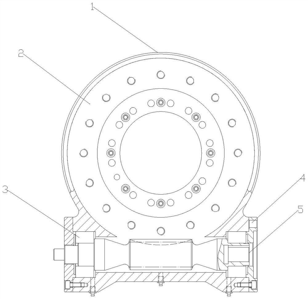
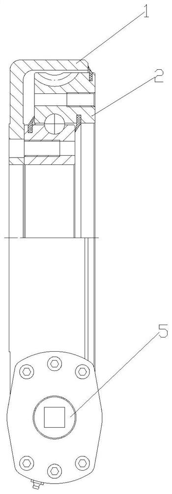
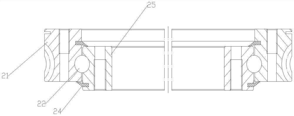
The invention discloses a slewing bearing worm wheel outer gear ring processing method and a rotary driving device. The processing method comprises the following steps: rough turning, semi finish turning, roller path thermal treatment, tempering, finish turning, hobbing, hole processing and roll path lathing and grinding. The rotary driving device comprises a worm wheel slewing bearing and a worm;conical roller bearings are arranged on the two side walls of the worm; a slewing bearing worm wheel outer gear ring is processed through a large-diameter hob; when the worm wheel and the worm drivefor operation, certain space exists between the dedendum circle of the worm wheel and the addendum circle of the worm, and an artificial oil culvert is formed in the space, so that the lubricating condition can be effectively improved and the actual contact area can be enlarged, the coefficient of friction and the contact stress value are reduced, and the purpose of improving the driving bearing capacity of the worm wheel and the worm is finally realized; and in addition, the worm wheel is processed by adopting the large-diameter hob, drum type modification is carried out in the tooth direction, and along with load increase, the contact spot becomes larger and larger, so that the bearing capacity of the worm wheel is improved, the transmission noise of a rod pair is lowered, and the service life is prolonged.

Description

technical field [0001] The invention relates to the field of rotary drive, in particular to a processing method for a rotary support worm gear outer ring gear and a rotary drive device. Background technique [0002] The slewing drive device is a new type of slewing mechanism, which plays an important role and position in the construction machinery industry. The main components of the general form of rotary drive are: worm, worm gear, housing, motor, bearing and other components, which can realize large reduction ratio transmission, so as to meet the requirements of low speed and large output torque. [0003] Ordinary worm gear transmission, the material of the worm gear is copper alloy, the worm has 45 steel, 50Mn, 42CrMo, etc. according to different working conditions, and the heat treatment form is generally quenching and tempering, quenching, nitriding, etc. The material of the worm gear in the worm gear transmission is generally 50Mn or 42CrMo, which is prone to glue wh...

Claims


Application Information

Patent Timeline
IPC IPC(8): B23P15/14F16H1/16F16H57/021
CPCB23P15/14F16H1/16F16H57/021
Inventor 许宁朱良银许丽华毕娟娟杨贤伟窦方浩
Owner MAANSHAN JINGYI ENG MACHINERY
Learn More