Ammonia stripping process and ammonia stripping device for high-concentration ammonia-nitrogen wastewater

An ammonia nitrogen wastewater, high concentration technology, applied in water pollutants, heating water/sewage treatment, degassed water/sewage treatment, etc., can solve the problems of high energy consumption, easy scaling and blocking of packing, and low ammonia stripping efficiency. , to achieve the effects of low energy consumption, good gas-water mixing effect, and avoidance of secondary pollution

Pending Publication Date: 2020-09-04
湖南迪亚环境工程股份有限公司
View PDF0 Cites 1 Cited by
  • Summary
  • Abstract
  • Description
  • Claims
  • Application Information

AI Technical Summary

Problems solved by technology

[0003] The purpose of the present invention is to provide an ammonia blow-off process and device for high-concentration ammonia-nitrogen wastewater, which can greatly improve the efficiency of ammonia blow-off. Efficiency, saving energy consumption, reducing operating costs

Method used


Image

  • Ammonia stripping process and ammonia stripping device for high-concentration ammonia-nitrogen wastewater
  • Ammonia stripping process and ammonia stripping device for high-concentration ammonia-nitrogen wastewater

Examples


Embodiment 1

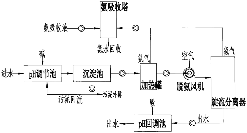
[0024] as attached figure 1 Shown, a kind of ammonia stripping process of high-concentration ammonia-nitrogen wastewater is characterized in that it comprises the following steps: (1) high-ammonia-nitrogen wastewater enters a pH adjustment tank, and simultaneously adds alkali to adjust the pH value of wastewater to the pH adjustment tank. (2) The effluent from the pH adjustment tank enters the sedimentation tank for mud-water separation to obtain supernatant and sedimentation sludge. (3) The supernatant of the sedimentation tank enters the heating tank to heat up, the sludge in the sedimentation tank is partially returned to the pH adjustment tank, and the remaining part is discharged. (4) The water out of the heating tank enters the deamination fan, and at the same time, air also enters the deamination fan, which is vigorously stirred and mixed in the deamination fan to form a gas-water mixture, and then enters the cyclone separator to separate into gas and water. The exhaus...

Embodiment 2

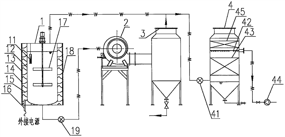
[0027] An ammonia stripping device for high-concentration ammonia-nitrogen wastewater, which includes a heating tank 1, a deammonization fan 2, a cyclone separator 3 and an ammonia absorption tower 4, the heating tank 1 and the deammonization fan 2 are connected by pipelines, and the connecting pipeline is equipped with There is a lifting pump 19, the ammonia removal fan 2 is connected to the cyclone 3 by pipelines, the exhaust end of the heating tank 1 and the exhaust end of the cyclone 3 are connected to the ammonia absorption tower 4 by pipelines, and an induced draft fan is installed on the connecting pipeline 41.

[0028] The heating tank 1 includes an inner tank body 12 and an outer tank body 13, a heating medium heat transfer oil 15 is filled between the inner tank body 12 and the outer tank body 13 and an electric heating tube 16 is provided, the inner tank body 12 is provided with a stirrer 17, and the outer tank body 13 The outside of the tank body 14 is provided wit...


PUM


Abstract

An ammonia stripping process for high-concentration ammonia-nitrogen wastewater comprises a pH regulating tank, a sedimentation tank, a heating tank, a deamination fan, a cyclone separator, a pH back-regulating tank and an ammonia absorption tower. PH and water temperature of inlet water are adjusted to create an optimal ammonia stripping condition. The sedimentation tank is provided with sludge backflow, and the use amount of alkali is saved. Inlet water is atomized in the deamination fan under the action of an impeller rotating at a high speed and is sufficiently and violently collided and mixed with air, free ammonia in the water is transferred from a liquid phase into a gas phase, enters the air and is separated from the water in the cyclone separator. The device is good in gas-water mixing effect, high in deamination efficiency and low in energy consumption. Ammonia gas generated in the wastewater treatment process is absorbed by clear water in the ammonia absorption tower, diluteammonia water is generated and recycled, resources are saved, and secondary pollution is avoided.

Description

technical field [0001] The invention relates to the technical field of high-concentration ammonia-nitrogen wastewater treatment, in particular to an ammonia stripping process for high-concentration ammonia-nitrogen wastewater and an ammonia stripping device for high-concentration ammonia-nitrogen wastewater. Background technique [0002] At present, the removal of ammonia nitrogen from high-concentration ammonia-nitrogen wastewater is a difficult problem in today's wastewater treatment. At present, the ammonia stripping tower is mainly used for ammonia stripping. The wastewater after pH adjustment enters from the water distributor at the upper part of the ammonia stripping tower. Enter from the lower part of the ammonia stripping tower, waste water and air flow in reverse in the ammonia stripping tower, contact the packing layer in the middle of the ammonia stripping tower for mass transfer, ammonia enters the gas phase from the liquid phase, and flows out of the ammonia stri...

Claims


Application Information

Patent Timeline
Patent Type & Authority Applications(China)
IPC IPC(8): C02F9/10C02F1/20C02F101/16
CPCC02F1/02C02F1/20C02F1/66C02F9/00C02F2001/007C02F2101/16
Inventor 周争孙铁刚孙翼虎陈光瑜蒋小建周上腾
Owner 湖南迪亚环境工程股份有限公司
Why Eureka
Try Eureka