Magnetic circuit designing method capable of adjusting magnetic interface form of magnetic conductive column Hall thruster

A technology of Hall thruster and magnetic circuit design, applied in thrust reversers, mechanical equipment, machines/engines, etc., can solve the problems of low electron utilization efficiency, high electron loss, low thruster discharge efficiency, etc. Utilize efficiency, reduce electron loss, and realize the effect of high-efficiency discharge

Active Publication Date: 2020-09-04
HARBIN INST OF TECH
View PDF7 Cites 15 Cited by
  • Summary
  • Abstract
  • Description
  • Claims
  • Application Information

AI Technical Summary

Problems solved by technology

[0005] The purpose of the present invention is to solve the problems of high electron loss, low electron utilization efficiency and low discharge efficiency of the thruster due to the existence of the magnetic interface in the existing magnetic column Hall thruster. Magnetic Circuit Design Method of Thruster Magnetic Interface Form

Method used


Image

  • Magnetic circuit designing method capable of adjusting magnetic interface form of magnetic conductive column Hall thruster
  • Magnetic circuit designing method capable of adjusting magnetic interface form of magnetic conductive column Hall thruster
  • Magnetic circuit designing method capable of adjusting magnetic interface form of magnetic conductive column Hall thruster

Examples


specific Embodiment approach 1

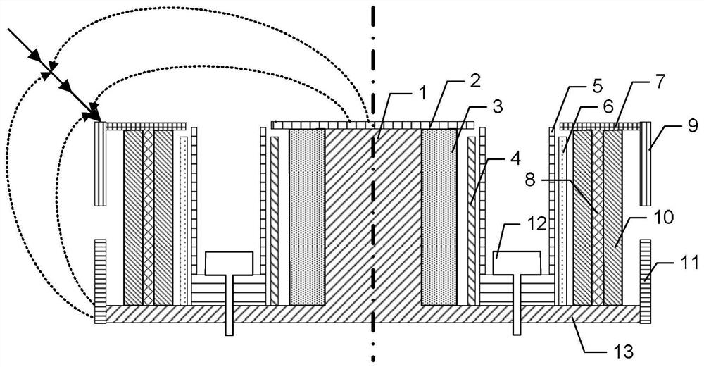
[0028] Specific implementation mode one: combine Figure 1 to Figure 9 Describe this embodiment, a magnetic circuit design method for adjusting the magnetic interface shape of the magnetic post Hall thruster described in this embodiment, the magnetic circuit structure design method is realized based on the magnetic post Hall thruster;

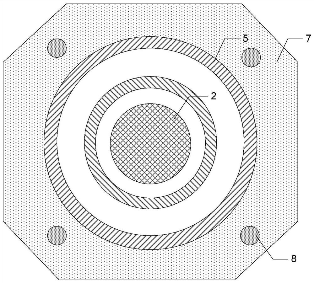
[0029] The magnetic column Hall thruster includes an inner iron core 1, an inner magnetic pole 2, an inner excitation coil 3, an inner magnetic screen 4, an integrated ceramic discharge channel 5, an outer magnetic screen 6, an outer magnetic pole 7, a magnetic column 8, External excitation coil 10, anode 12 and bottom plate 13;

[0030] The inner iron core 1 is cylindrical, and the inner iron core 1 is vertically fixed on the bottom plate 13, and the inner iron core 1 and the bottom plate 13 are integrally structured;

[0031] The inner magnetic pole 2 is arranged on the top of the inner iron core 1, the inner excitation coil 3 is wound on th...

specific Embodiment approach 2

[0046] Specific embodiment 2: This embodiment is to further limit the magnetic circuit design method for adjusting the magnetic interface form of the magnetic column Hall thruster described in the specific embodiment 1. In this embodiment, the inner iron core 1, The inner magnetic pole 2, the inner magnetic shield 4, the outer magnetic shield 6, the outer magnetic pole 7, the magnetic pole 8, the upper shell 9 and the lower shell 11 are respectively made of DT4C pure iron.

[0047] In this embodiment, the above-mentioned settings ensure the magnetic permeability and high temperature resistance of the structure, while ensuring the strength of the structure, effectively ensuring the stability of magnetic permeability, and improving the ability to resist high temperature and particle bombardment.

specific Embodiment approach 3

[0048] Specific embodiment three: This embodiment is to further limit the magnetic circuit design method for adjusting the magnetic interface shape of the magnetic column Hall thruster described in the specific embodiment one. In this embodiment, the integrated ceramic discharge channel 5 Made from a mixture of boron nitride and silicon dioxide.

[0049] In this embodiment, the hardness and compactness of the ceramic tube are ensured through the above configuration, and the ability to resist high temperature and particle bombardment is effectively improved.


PUM

PropertyMeasurementUnit
thicknessaaaaaaaaaa
heightaaaaaaaaaa
heightaaaaaaaaaa

Abstract

The invention discloses a magnetic circuit designing method capable of adjusting the magnetic interface form of a magnetic conductive column Hall thruster, relates to a magnetic circuit structural design technology for the magnetic interface form of the Hall thruster, and aims to solve the problems of high electron loss, low electron utilization efficiency and low thruster discharging efficiency due to a magnetic interface existing in an existing magnetic conductive column Hall thruster. According to the magnetic circuit designing method, upper side shells or lower side shells are added on themagnetic conductive column Hall thruster; the positions, heights and thicknesses of the upper side shells or the lower side shells are changed to realize the adjustment of the form of the magnetic interface; the upper side shells are added in order to increase the angle between the magnetic interface and the axis of the thruster; the lower side shells are added in order to reduce the angle between the magnetic interface and the axis of the thruster; the upper side shells are arranged on the outer side of an outer magnet exciting coil at intervals, and are in contact with the outer edge of anouter magnetic pole; and the lower side shells are arranged on the outer side of the outer magnet exciting coil at intervals, and are in contact with the outer edge of a bottom plate. The magnetic circuit designing method has the beneficial effects of reducing the electron loss, improving the electron utilizing efficiency, and realizing high efficiency of the thruster.

Description

technical field [0001] The invention relates to a magnetic circuit structure design technology of the magnetic interface form of a Hall thruster. Background technique [0002] The Hall thruster is an electric propulsion device that uses an orthogonal electromagnetic field to ionize and accelerate the working gas to generate thrust. It is mainly used in the field of aerospace propulsion; the Hall thruster forms an orthogonal electromagnetic field inside the channel, and the electrons emitted by the cathode reach the channel. During the process of the bottom anode, it is constrained by the magnetic field and performs Larmor orbital motion around the magnetic force line; the propellant is injected from the bottom of the channel, and the neutral atoms and electrons collide and ionize in the channel, producing a large number of ions and electrons; the effect of ions on the axial electric field It is ejected at a high speed to form a plume, thereby generating thrust; the Hall thru...

Claims


Application Information

Patent Timeline
Patent Type & Authority Applications(China)
IPC IPC(8): F03H1/00
CPCF03H1/0087
Inventor 李鸿钟超丁永杰魏立秋于达仁
Owner HARBIN INST OF TECH
Why Eureka
Try Eureka