Using convolution neural networks for on-the-fly single particle reconstruction

A neural network and artificial neural network technology, applied in the field of particle selection, can solve problems such as difficulty in developing, identifying and classifying different particles

Active Publication Date: 2020-09-04
FEI CO
View PDF6 Cites 0 Cited by
  • Summary
  • Abstract
  • Description
  • Claims
  • Application Information

AI Technical Summary

Problems solved by technology

Even when a suitable training set of specific particles is available, it is still difficult to develop a CNN for identifying and classifying different particles

Method used


Image

  • Using convolution neural networks for on-the-fly single particle reconstruction
  • Using convolution neural networks for on-the-fly single particle reconstruction
  • Using convolution neural networks for on-the-fly single particle reconstruction

Examples


example 1

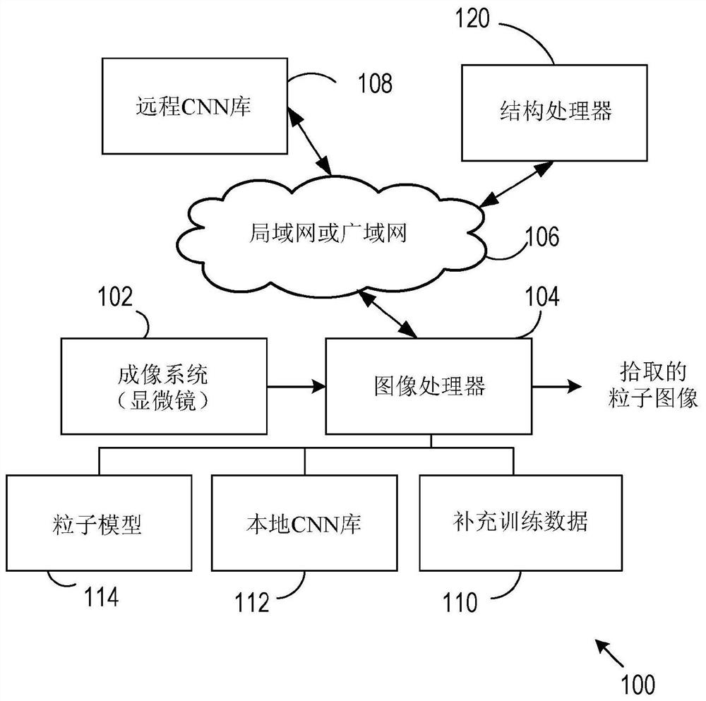
[0026] refer to figure 1 , a representative system 100 for picking up particles for structure determination or other applications includes an imaging system 102, typically a transmission electron microscope (TEM), which provides an image of a particle-laden substrate to Image processor 104 to identify expected types of particles and reject undesired particles. A TEM or other electron microscope generally includes an electron beam source, electron optics, and an electron detection system that captures or produces electron beam-based images, also referred to herein as an electron beam column. Particle identification can be challenging due to the generally limited quality of images produced by the imaging system 102 . The image processor 104 may be implemented in the form of a processor associated with the imaging system 102 or associated with a separate local processing device as discussed, or associated with a remote processor coupled by a local or wide area network 106 to Th...

example 2

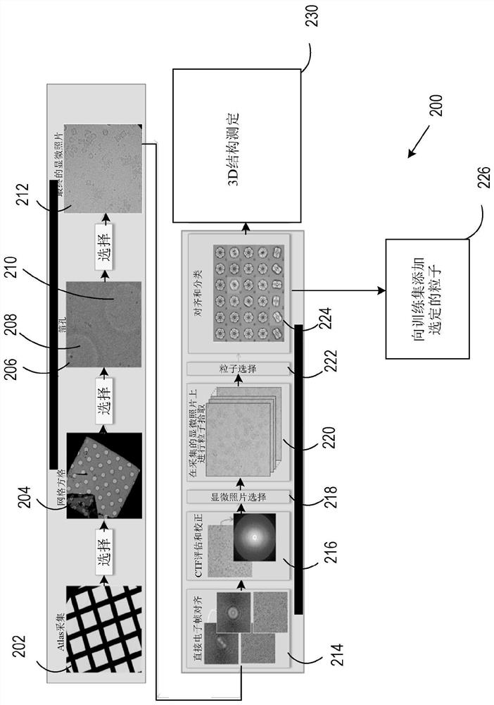
[0029] refer to figure 2 , a representative workflow 200 for particle picking includes providing a TEM grid 202 on which selected particles are distributed. In some examples, TEM grid 202 is a so-called "porous" carbon-coated TEM support or foil that contains a plurality of pores. Particles may be retained in the ice layer at some or all of the holes on grid 202 or at other locations. One or more images (also referred to as "micrographs") of a network region are obtained at 204, and specific mesh regions are selected at 206. Such as figure 2 As shown, image portions 208 , 210 correspond to holes in network 202 . At 212 a final portion of an image or a corresponding portion of a series of images is selected. In some cases, photomicrographs were not selected due to significant defocus; substantial ice contamination; or images containing only carbon support and no pore regions. With a perfect particle picking method, manual selection of photomicrographs may not be necessar...

example 3

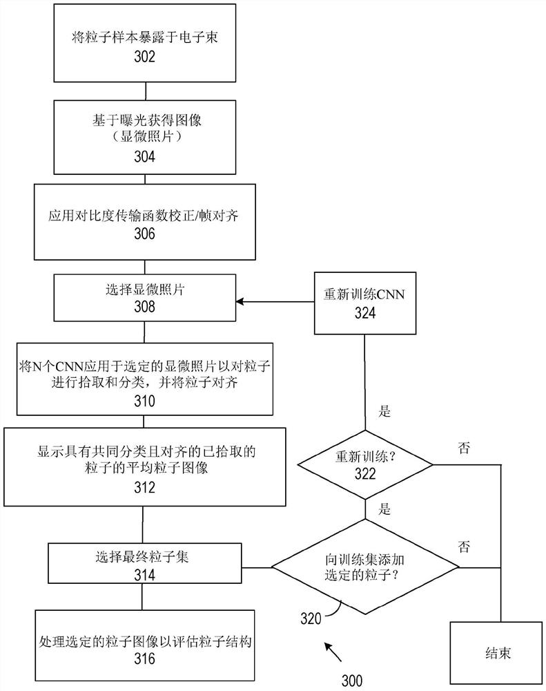
[0031] refer to image 3 , method 300 of selecting particles of a particular type includes exposing one or more particle samples to an electron beam at 302 and obtaining an associated image at 304 . At 306, a contrast transfer function correction is applied to the images, and image frames from the series of images are aligned and combined. At 308, some images (micrographs) are selected for further processing. At 310, multiple CNNs are applied to selected images to pick and classify particle images and indicate particle alignment. At 312, an average particle image of common types and arrangements of particles can be displayed. At 314, a final particle set of preferred particle types is selected, and at 316, some or all of the selected particle images may be used to evaluate particle structure.

[0032] After the final set of particles is selected at 314, the selected set of particles may be used to refine the neural network for particle selection, or to train or refine anoth...


PUM


Abstract

Convolutional neural networks (CNNs) of a set of CNNs are evaluated using a test set of images (electron micrographs) associated with a selected particle type. A preferred CNN is selected based on theevaluation and used for processing electron micrographs of test samples. The test set of images can be obtained by manual selection or generated using a model of the selected particle type. Upon selection of images using the preferred CNN in processing additional electron micrographs, the selected images can be added to a training set or used as an additional training set to retrain the preferredCNN. In some examples, only selected layers of the preferred CNN are retrained. In other examples, two dimensional projections of based on particles of similar structure are used for CNN training orretraining.

Description

technical field [0001] The present disclosure relates to particle selection as in cryo-electron tomography of biological particles. Background technique [0002] Electron microscopy has been used to study the structure of biological particles. Typically, particle specimens are kept at low temperatures and images are acquired with low electron beam doses (although images can be acquired using ions or other charged particle beams (CPB)) to avoid altering the specimen. Consequently, images containing such particles have low contrast and low signal-to-noise ratio, and it is difficult to reliably select instances of expected particles in images for structure determination. In many cases, users select and study large numbers of particles through a tedious, time-consuming manual process. In other cases, convolutional neural networks (CNNs) have been used to identify desired particles. Unfortunately, training a CNN often requires identifying and / or classifying hundreds or thousan...

Claims


Application Information

Patent Timeline
Patent Type & Authority Applications(China)
IPC IPC(8): G06T11/00G06K9/62G06N3/04G06N3/08G06V10/764
CPCG06T11/006G06T11/008G06N3/08G06N3/045G06F18/241G01N15/1475G01N2015/1006G06V10/454G06V10/82G06V10/764G06F18/2413G06T7/0012G06T2207/20084G06T11/003G01N15/10G06T2207/30168G06T2207/10056G06T2207/20081G06V20/698G06V20/64G06F18/217G06F18/285G06F18/2148
Inventor J.弗拉纳根E.弗兰肯M.皮门
Owner FEI CO
Why Eureka
Try Eureka