Supercharge Your Innovation With Domain-Expert AI Agents!

Electrode structure for generating pulse point light source

A technology of electrode structure and point light source, which is applied to X-ray tube electrodes, X-ray tube structure circuit components, circuits, etc., can solve problems such as low experimental efficiency, unstable position of X-ray light emitting point, and off-center point of crossing point, etc. , to achieve the effect of improving experimental efficiency, easy and accurate load problems, and avoiding errors

Pending Publication Date: 2020-09-04
CHINA INSTITUTE OF ATOMIC ENERGY
View PDF0 Cites 0 Cited by
  • Summary
  • Abstract
  • Description
  • Claims
  • Application Information

AI Technical Summary

Problems solved by technology

[0004] Aiming at the deficiencies in the prior art, the present invention proposes an electrode structure for generating pulsed point light sources, with the purpose of solving the problem that the crossing point of the multi-filament crossing structure deviates from the center point, resulting in unstable position of the X-ray light exit point and low experimental efficiency

Method used


Image

  • Electrode structure for generating pulse point light source
  • Electrode structure for generating pulse point light source
  • Electrode structure for generating pulse point light source

Examples


Embodiment 1

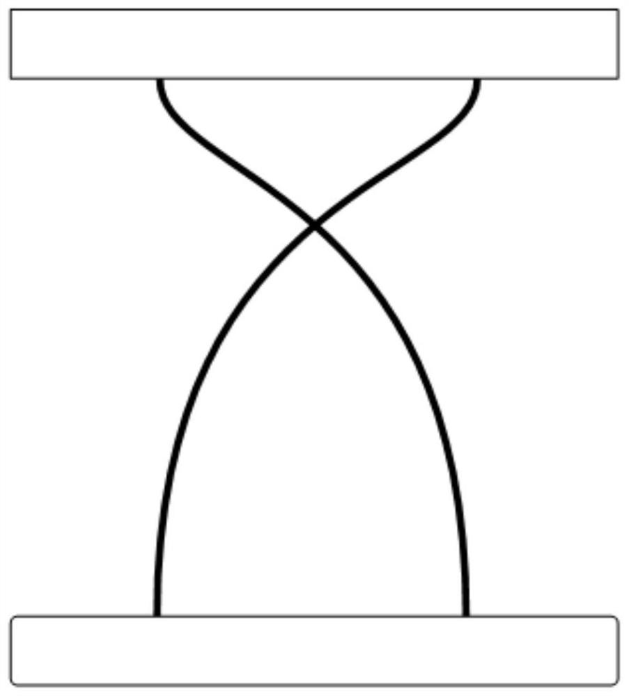
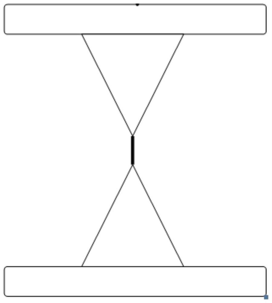
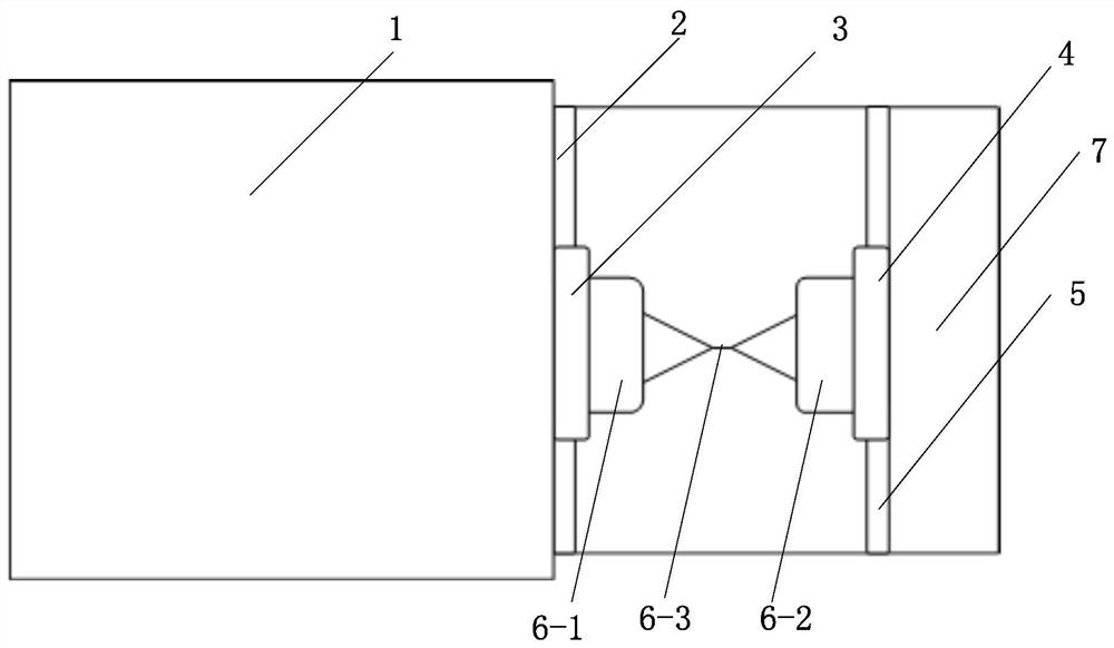
[0025] according to Figure 1a As shown in the previous conventional experiments, it was found that under the action of strong current pulse waves, the intersecting metal wires will first explode at the intersection point, and the gasified metal wires will instantly condense into high-temperature and high-density plasma under the action of magnetic field pressure. , radiate pulsed X-rays, the whole physical process occurs within the distance of 1mm up and down at the fork point, according to this phenomenon, a conical electrode loading structure is developed. It adopts conical electrodes as cathode and anode. The cone tips of conical cathode and anode need to be aligned and in a horizontal plane. Only one metal wire is installed between the conical cathode and anode to form the load. It can generate stable under the driving of strong current pulse. The pulsed point light source is quick and easy to install, and can completely replace the original cross wire load structure. In ...

Embodiment 2

[0027] Embodiment 2: wire changing operation

[0028] 1. Disassemble the return electrode;

[0029] 2. Disassemble the cathode holder;

[0030] 3. After the cathode is installed on the wire, the cathode holder is installed into the output electrode screw hole;

[0031] 4 After the cathode outlet wire is loaded into the anode wire hole, the return electrode is fixedly installed with the metal flange.


PUM

PropertyMeasurementUnit
diameteraaaaaaaaaa
diameteraaaaaaaaaa
diameteraaaaaaaaaa

Abstract

The invention discloses an electrode structure for generating a pulse point light source. The electrode structure comprises a heavy-current pulse source, a vacuum cavity, an output electrode, a conical cold cathode, a conical cold anode and a metal flange; a conical anode arranged opposite to the conical tip direction of the conical cold cathode serves as a loop electrode; the conical cold cathodeand the conical anode are equal in size, the two conical tips of the conical cold cathode and the conical anode are located in the same straight line, the conical tip parts of the conical cold cathode and the conical anode are provided with wire holes respectively, a metal wire is connected between the conical cold cathode and the conical anode through the wire holes, and therefore a wire load isformed. The loop electrode forms a loop through the vacuum cavity shell. According to the invention, an element substitution method is adopted; an unexpected effect is achieved: only one metal wire and two inherent electrodes are needed to replace the original multi-wire structure by replacing the original multi-wire part with the inherent electrodes, and as the inherent electrode design is adopted, the installation efficiency and the installation precision are effectively improved, and errors caused by fork point position deformation in the installation process of the multi-wire cross structure are avoided.

Description

technical field [0001] The invention relates to the field of pulsed rays, more specifically, it relates to an electrode structure for generating pulsed point light sources. Background technique [0002] In the pulsed high-voltage technology, in order to obtain a pulsed X-ray point light source with a diameter of 10 μm-30 μm, a high-current pulse source is often used to drive a crossed wire load to obtain it. The reason for using a crossed wire load to obtain an X-ray point light source is: in the past In conventional experiments, it was found that under the action of strong current pulse waves, crossing metal wires will firstly explode at the intersection point, and the vaporized metal wires will instantly condense into high-temperature and high-density plasma under the action of magnetic field pressure, and the radiation pulse For X-rays, the entire physical process occurs within a distance of 1mm up and down at the fork point. According to this phenomenon, the prior art us...

Claims


Application Information

Patent Timeline
Patent Type & Authority Applications(China)
IPC IPC(8): H01J35/06H01J35/08H01J35/22H01J35/02
CPCH01J35/064H01J35/08H01J35/025H01J35/22
Inventor 邹俭郑侠王川张天爵
Owner CHINA INSTITUTE OF ATOMIC ENERGY
Features
  • R&D
  • Intellectual Property
  • Life Sciences
  • Materials
  • Tech Scout
  • Unparalleled Data Quality
  • Higher Quality Content
  • 60% Fewer Hallucinations
Learn More