Elastic centralizer

A centralizer and elastic technology, used in drilling equipment, earthmoving, drill pipe, etc., can solve the problems of difficult to scrape off dirt, easy to get stuck inside the oil pipe, damage the oil pipe, etc., so as to avoid the rigidity from changing and keep the movement smooth. , the effect of improving oil production efficiency

Active Publication Date: 2020-09-08
大庆市宏博晟达石油机械设备有限公司
View PDF6 Cites 5 Cited by
  • Summary
  • Abstract
  • Description
  • Claims
  • Application Information

AI Technical Summary

Problems solved by technology

[0002] The sucker rod centralizer is an anti-eccentric downhole tool for pumping wells, which is suitable for pumping wells with eccentric wear. The existing oil rod centralizer is usually equipped with a set of scrapers to clean the dirt on the inner wall of the oil pipe during use. However, the diameter of the scraper on the existing oil rod centralizer cannot be changed. When the dirt in the oil pipe has a certain thickness, it is difficult for the scraper to scrape off the dirt on the inner wall of the oil pipe, thereby increasing the time when the oil rod centralizer moves. resistance, and when the inner wall of the oil pipe changes in diameter, if the oil rod centralizer cannot change its own diameter, it is easy to get stuck inside the oil pipe and damage the oil pipe. The elastic centralizer currently used uses springs or elastic discs to improve the above Problem, there is still the problem of elastic failure due to impurities inserted into the spring and elastic disc

Method used


Image

  • Elastic centralizer
  • Elastic centralizer
  • Elastic centralizer

Examples


Embodiment Construction

[0016] The present invention will be further described below in conjunction with accompanying drawing:

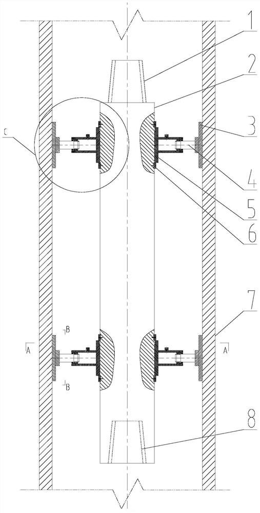
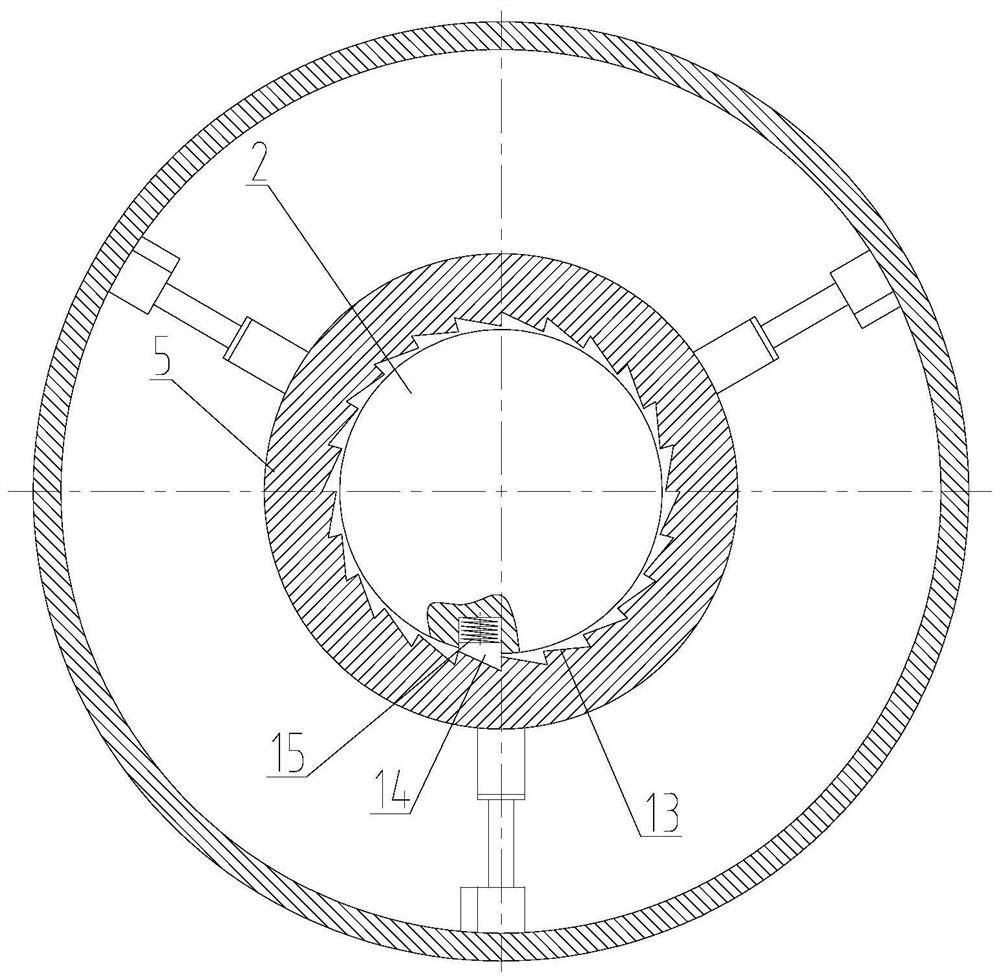
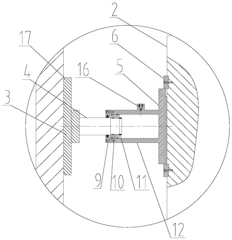
[0017] Depend on figure 1 combine Figure 2-4 As shown, an elastic centralizer includes a body 2, an upper joint 1 is provided on the upper part of the main body 2, a lower joint 8 is provided on the lower part of the main body 2, and a rotating sleeve 5 is respectively arranged on the upper and lower sides of the cylindrical section of the main body 2, and each rotating sleeve 5 There are positioning sleeves 6 on the upper and lower sides, and the positioning sleeves 6 are fixedly connected to the body 2 through screws. There is a counterbore, in which there are springs 15 and one-way teeth 14, and the inner hole of the rotating sleeve 5 is evenly distributed with one-way tooth grooves 13 and one-way teeth 14 in the circumferential direction. The inner hole of the sleeve 5 is connected with the outer surface of the body 2 by clearance fit;

[0018] There are three unifo...


PUM


Abstract

The invention discloses an elastic centralizer, and relates to the technical field of oil extraction. The elastic centralizer is characterized in that a lower shell and a gathering and transportationpipeline are welded together, each of the upper and lower portions of the cylindrical section of a body is provided with a rotating sleeve, the upper and lower portions of each rotating sleeve are provided with positioning sleeves, and three air cylinder barrels, pistons, piston rods and push plates are arranged on the outer circle surfaces of the rotating sleeves correspondingly. The elastic centralizer has the beneficial effects that the push plates rotate circumferentially along a fixed rotation direction, meanwhile, the push plates move up and down, oil wax and impurities attached to the inner walls of oil pipes are scraped off by the push plates in the circumferential direction and the length direction of the oil pipes, so that the smoothness of a crude oil production pipeline is kept, the oil extraction efficiency is improved, the energy consumption is reduced, and the air pressure in the air cylinder barrels is adjusted; the elastic centralizer is suitable for various oil wellsand oil pipes with different diameters, when the centralizer passes through the narrow parts of the inner walls of the oil pipes or the bent parts of a horizontal well, the elastic support of the compressed air can adapt to the change, so that the clamping stagnation phenomenon is avoided, the smooth movement of a sucker rod is kept, and the problems that the rigidity of a metal elastic element cannot be changed, and the metal elastic element is easily blocked by impurities and loses elasticity are avoided.

Description

Technical field: [0001] The invention relates to the technical field of oil production, in particular to an elastic centralizer. Background technique: [0002] The sucker rod centralizer is an anti-eccentric downhole tool for pumping wells, which is suitable for pumping wells with eccentric wear. The existing oil rod centralizer is usually equipped with a set of scrapers to clean the dirt on the inner wall of the oil pipe during use. However, the diameter of the scraper on the existing oil rod centralizer cannot be changed. When the dirt in the oil pipe has a certain thickness, it is difficult for the scraper to scrape off the dirt on the inner wall of the oil pipe, thereby increasing the time when the oil rod centralizer moves. resistance, and when the inner wall of the oil pipe changes in diameter, if the oil rod centralizer cannot change its own diameter, it is easy to get stuck inside the oil pipe and damage the oil pipe. The elastic centralizer currently used uses sprin...

Claims


Application Information

Patent Timeline
Patent Type & Authority Applications(China)
IPC IPC(8): E21B17/10
CPCE21B17/1042
Inventor 肖云东
Owner 大庆市宏博晟达石油机械设备有限公司
Why Eureka
Try Eureka