Permanent magnet compression molding method and device

A technology of pressing and forming permanent magnets, which is applied in the direction of magnetic objects, inductors/transformers/magnets, circuits, etc. It can solve the problems that the process cannot meet the actual needs of the project, the preparation structure is large in size, and the performance of the magnet is limited, so as to improve the molding process. Compression force, high flexibility, and the effect of increasing the density of permanent magnets

Active Publication Date: 2020-09-08
HUAZHONG UNIV OF SCI & TECH
View PDF11 Cites 5 Cited by
  • Summary
  • Abstract
  • Description
  • Claims
  • Application Information

AI Technical Summary

Problems solved by technology

[0006] The present invention provides a permanent magnet pressing molding method and device, which are used to solve the technical problem that the existing permanent magnet pressing molding process cannot meet the actual needs of the project due to the large volume of the prepared structure and the limited performance of the produced magnet.

Method used


Image

  • Permanent magnet compression molding method and device
  • Permanent magnet compression molding method and device
  • Permanent magnet compression molding method and device

Examples


Embodiment 1

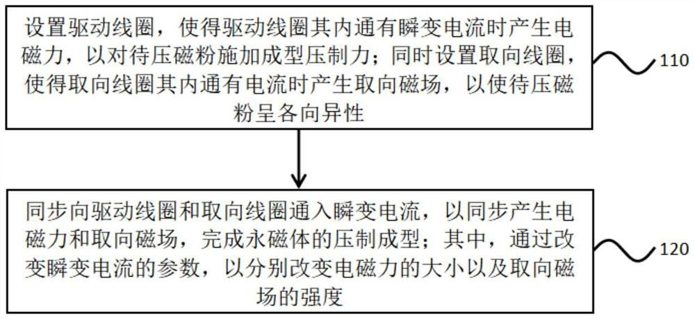
[0039] A permanent magnet press molding method 100, such as figure 1 shown, including:

[0040] Step 110, setting the driving coil so that an electromagnetic force is generated when there is a transient current in the driving coil, so as to apply a forming pressing force to the magnetic powder to be pressed; at the same time, setting an orientation coil so that an orientation magnetic field is generated when a current is passed in the orientation coil, so that Make the magnetic powder to be pressed anisotropic;

[0041] Step 120, synchronously feed the transient current to the drive coil and the orientation coil to synchronously generate the electromagnetic force and the orientation magnetic field, and complete the press molding of the permanent magnet; wherein, by changing the parameters of the transient current, the magnitude of the electromagnetic force and The strength of the orientation magnetic field.

[0042] An electromagnetic coil is used to generate an orientation ...

Embodiment 2

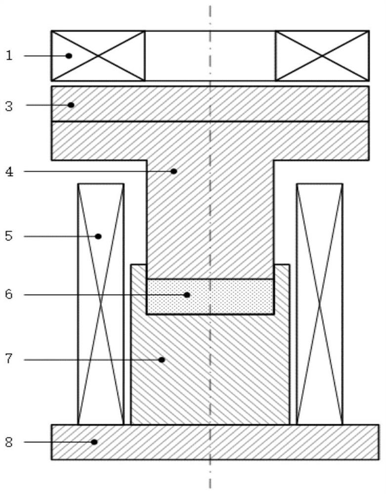
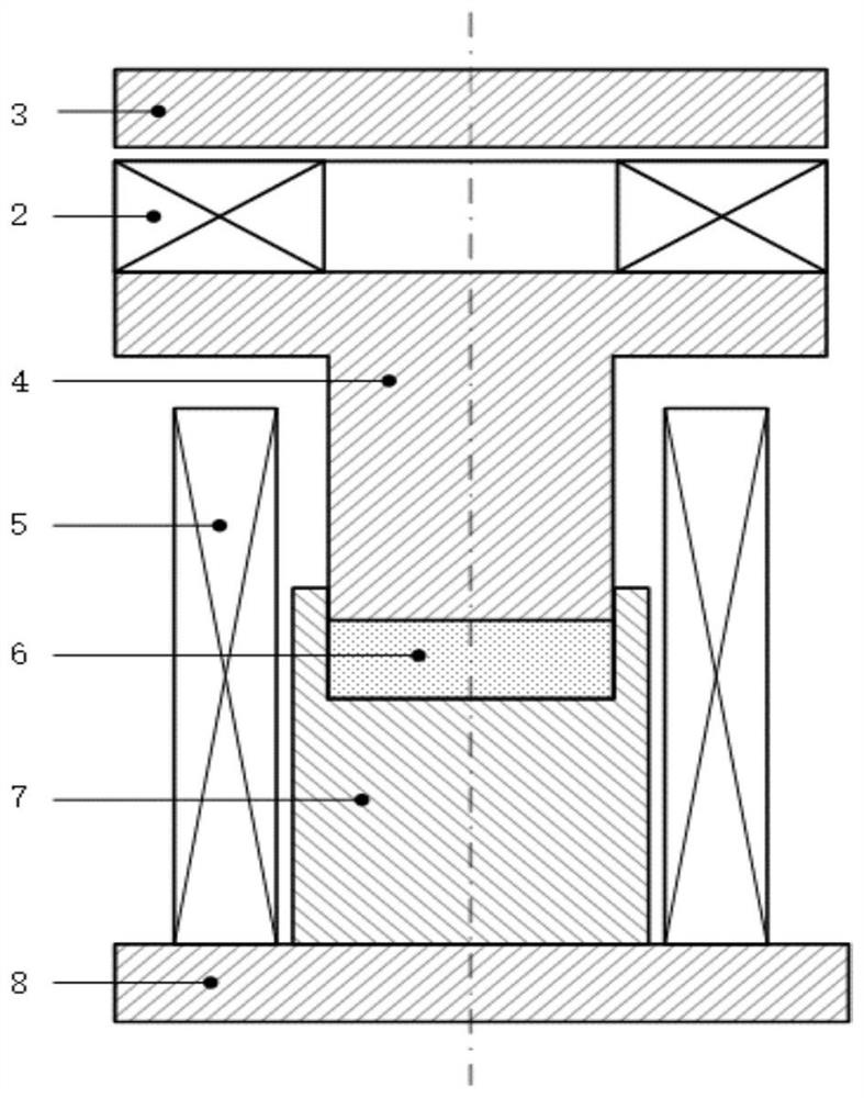
[0058] A permanent magnet pressing and forming device includes: a driving module, a pressure head, a mold, and an orientation coil. Among them, the center of the mold is provided with a groove for filling the magnetic powder to be pressed; the bottom of the indenter is in contact with the magnetic powder to be pressed, and the top is in contact with one end of the drive module, and the central axes of the indenter and the groove coincide; The electromagnetic force in the permanent magnet pressing molding method described in the first embodiment above is used to drive the pressure head to apply the molding pressing force to the magnetic powder to be pressed; Orientation magnetic field in permanent magnet press-forming method.

[0059] The driving module includes: two driving coils, or one driving coil, or one driving coil and a driving board. It is used to pass in transient current to generate transient magnetic field, cooperate with the drive board to generate electromagnetic...


PUM


Abstract

The invention belongs to the field of permanent magnet compression molding, and particularly relates to a permanent magnet compression molding method which comprises the following steps: arranging a driving coil to generate an electromagnetic force when a transient current is introduced into the driving coil so as to apply a molding pressing force to to-be-pressed magnetic powder; arranging an orientation coil and generating an orientation magnetic field when a transient current is introduced into the orientation coil to enable the to-be-pressed magnetic powder to be anisotropic; synchronouslyintroducing transient currents into the driving coil and the orientation coil so as to synchronously generate an electromagnetic force and an orientation magnetic field and finish compression moldingof the permanent magnet. The magnitude of the electromagnetic force and the intensity of the oriented magnetic field are respectively changed by changing the peak value of the transient current. According to the method, the transient coil is adopted to generate the oriented magnetic field, the oriented magnetic field can reach very high, and the magnetic performance of the permanent magnet is improved; the transient coil is adopted to generate electromagnetic force to press the magnetic powder, so that the density of the permanent magnet is improved, and the pressing time is short; and problems that an electromagnet in the prior art is large in size and cannot further improve the orientation magnetic field intensity are solved, and practicability is high.

Description

technical field [0001] The invention belongs to the field of permanent magnet compression molding, and more specifically relates to a permanent magnet compression molding method and device. Background technique [0002] At present, the permanent magnet production processes involved in industry mainly include sintering, bonding, casting and hot pressing and thermal deformation. Among them, the sintering process is the most widely used production process. Most of the sintered permanent magnets are anisotropic magnets. The loose magnetic powder is placed in the cavity of the press to form it under the action of an external orientation magnetic field and pressure. The magnetic powder After oriented pressing and molding, it will be sintered into a sintered permanent magnet. [0003] The bonding process is to place the mixture of magnetic powder and binder in the cavity of the press to form it under pressure without going through the sintering process. If the magnetic powder has ...

Claims


Application Information

Patent Timeline
Patent Type & Authority Applications(China)
IPC IPC(8): H01F13/00H01F41/02
CPCH01F13/003H01F41/0266H01F41/0273B22F3/087B22F2999/00B30B11/008C22C2202/02B22F3/02B22F2003/033B22F3/03B30B1/42B22F2202/05B22F3/003
Inventor 李亮吕以亮吴添
Owner HUAZHONG UNIV OF SCI & TECH
Why Eureka
Try Eureka