Rotary part on-machine precise and quick alignment device and method

A kind of parts and precise technology, which is applied in the field of on-machine accurate and fast alignment devices for rotary parts, can solve problems such as tool breakage, parts wall thickness error that cannot meet processing requirements, and unstable processing surface quality, etc., to achieve accurate and fast adjustment, Easy to automatically adjust, the adjustment process is simple, convenient and fast

Active Publication Date: 2020-09-11
DALIAN UNIV OF TECH
View PDF11 Cites 9 Cited by
  • Summary
  • Abstract
  • Description
  • Claims
  • Application Information

AI Technical Summary

Problems solved by technology

[0003] At present, during precision/ultra-precision turning or grinding, the rotary parts are mainly detected by technical operators using dial gauges, dial gauges, etc. The tool with a softer material hits the outer circle of the part to adjust the position of the part to ensure that the coincidence error between the center line of rotation of the part and the center line of rotation of the machine tool spindle is within a small range. This adjustment process belongs to the alignment of the part clamping process. It is also an important process in the processing of this type of parts. The existing manual alignment method, high-tech operators can fine-tune the alignment accuracy to reach the micron level. Although it is difficult, and due to the limitation of alignment accuracy, it must be A larger machining allowance is reserved in the subsequent machining process, which will inevitably lead to a large amount of material removal in the precision/ult

Method used


Image

  • Rotary part on-machine precise and quick alignment device and method
  • Rotary part on-machine precise and quick alignment device and method
  • Rotary part on-machine precise and quick alignment device and method

Examples


Example Embodiment

[0042] In order to make the objectives, technical solutions, and advantages of the embodiments of the present invention clearer, the technical solutions in the embodiments of the present invention will be described clearly and completely in conjunction with the description of the drawings of the present invention. The specific embodiments described below are only The explanation of the present invention is not intended to limit the present invention.

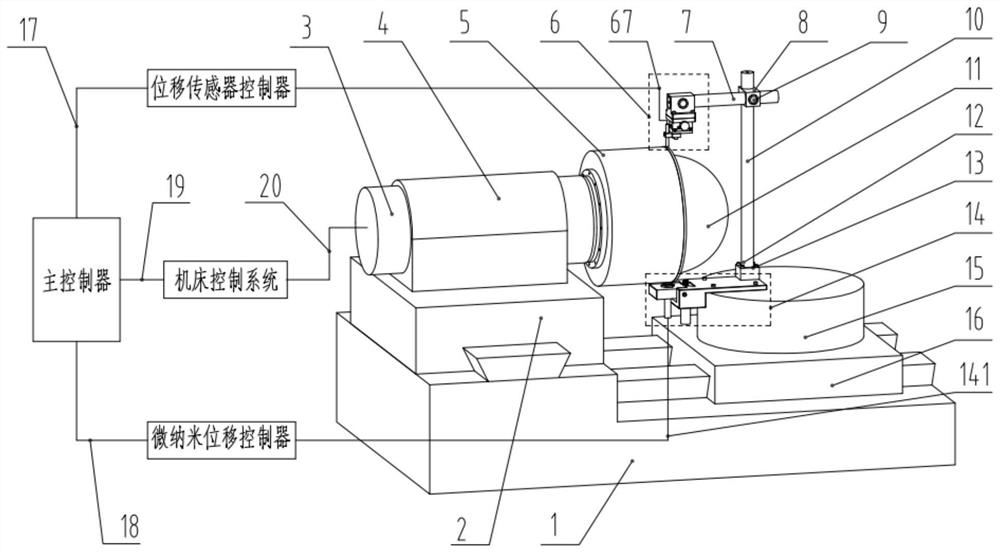
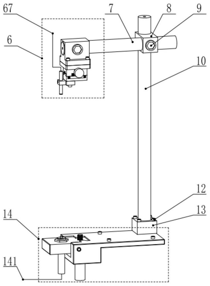
[0043] Such as Figure 1-7 As shown, an on-machine precise alignment device for rotating parts includes three main parts: a main control system, a high-precision displacement detection device 6 and a micro-nano displacement adjustment device 14;

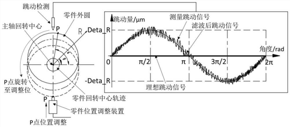
[0044] The main control system is used to control the high-precision displacement detection device 6 to detect the outer circle runout of the rotating parts 11, and to perform data analysis and processing on the detection results, and then control the machine tool spindle (C axis) 3 to rota...


PUM


Abstract

The invention discloses a rotary part on-machine precise and quick alignment device and method, and belongs to the technical field of precision/ultra-precision machining. The rotary part on-machine precise and quick alignment device comprises a main controller, a high-precision displacement detection device and a micro-nano displacement adjusting device. The rotary part on-machine precise and quick alignment method comprises the steps that firstly, the high-precision displacement detection device is controlled by the main controller to conduct data acquisition on the excircle runout of a part,acquired data are subjected to low-pass filtering treatment and then least square fitting treatment is conducted; then the maximum deviation of the part and the corresponding deviation angle are calculated, a machine tool main shaft is controlled by the main controller to rotate to be located at the appointed angle, the micro-nano displacement adjusting device is adopted to adjust the displacement of the part within the nanometer-grade to micron-grade range, and then the excircle of the part is detected after adjustment is accomplished; and finally, the adjusting process is repeated until theexcircle runout of the rotary part meets the precision/ultra-precision machining requirement. The rotary part on-machine precise and quick alignment device and method have the advantages of being high in precision, being capable of achieving the submicron grade and even the nanometer grade, being convenient and fast to adjust, high in repeatability of the adjustment accuracy and low in dependenceof the technology of an operator, and easily achieving the automation.

Description

technical field [0001] The invention belongs to the technical field of precision / ultra-precision machining, and in particular relates to an on-machine accurate and fast alignment device and method for rotary parts. Background technique [0002] High-precision rotary parts, such as: rings, shafts, bushings, spherical or aspherical parts, casings, etc., are widely used in aerospace, military, medical, precision instruments and precision physical experiments and other fields. Performance requirements put forward extremely high processing requirements for this type of rotary parts, including the roundness, cylindricity, profile error and wall thickness error of the part, and its dimensional accuracy and shape accuracy reach the micron submicron level, or even nanometer At present, such parts are mainly processed by precision / ultra-precision turning or grinding. [0003] At present, during precision / ultra-precision turning or grinding, the rotary parts are mainly detected by tec...

Claims


Application Information

Patent Timeline
IPC IPC(8): B23Q3/12B23Q15/22B23Q17/22
CPCB23Q3/12B23Q15/22B23Q17/22
Inventor 康仁科郭江朱祥龙焦振华
Owner DALIAN UNIV OF TECH
Why Eureka
Try Eureka