
A glass fiber drawing machine and its breaking device

A glass fiber and wire drawing machine technology, applied in glass production, glass manufacturing equipment, manufacturing tools, etc., can solve problems affecting glass fiber production cost, waste of resources, difficulty in quickly cutting waste wire, etc., to avoid waste of glass fiber, reduce The amount of waste silk and the effect of reducing the amount of waste silk

Active Publication Date: 2022-07-05
CHONGQING POLYCOMP INT
View PDF3 Cites 0 Cited by
  • Summary
  • Abstract
  • Description
  • Claims
  • Application Information

AI Technical Summary

Problems solved by technology

The outer periphery of the existing wire breaking device is only provided with a waste wire ring for accommodating waste wire. The waste wire ring is in the shape of a ring, and the outer circumference has several broken wire grooves extending in the axial direction. It is difficult to quickly cut the waste wire only by using the broken wire grooves. As a result, a large amount of waste wires are wound around the periphery of the existing wire breaking device, resulting in waste of resources and affecting the production cost of glass fibers

Method used


Image

  • A glass fiber drawing machine and its breaking device
  • A glass fiber drawing machine and its breaking device
  • A glass fiber drawing machine and its breaking device

Examples


Embodiment Construction

[0029] The technical solutions in the embodiments of the present invention will be clearly and completely described below with reference to the accompanying drawings in the embodiments of the present invention. Obviously, the described embodiments are only a part of the embodiments of the present invention, but not all of the embodiments. Based on the embodiments of the present invention, all other embodiments obtained by those of ordinary skill in the art without creative efforts shall fall within the protection scope of the present invention.

[0030] In order to make those skilled in the art better understand the solution of the present invention, the present invention will be further described in detail below with reference to the accompanying drawings and specific embodiments.

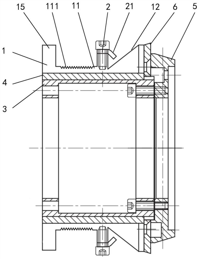
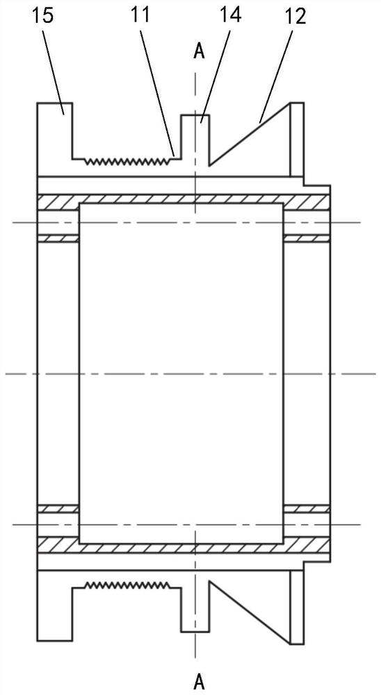
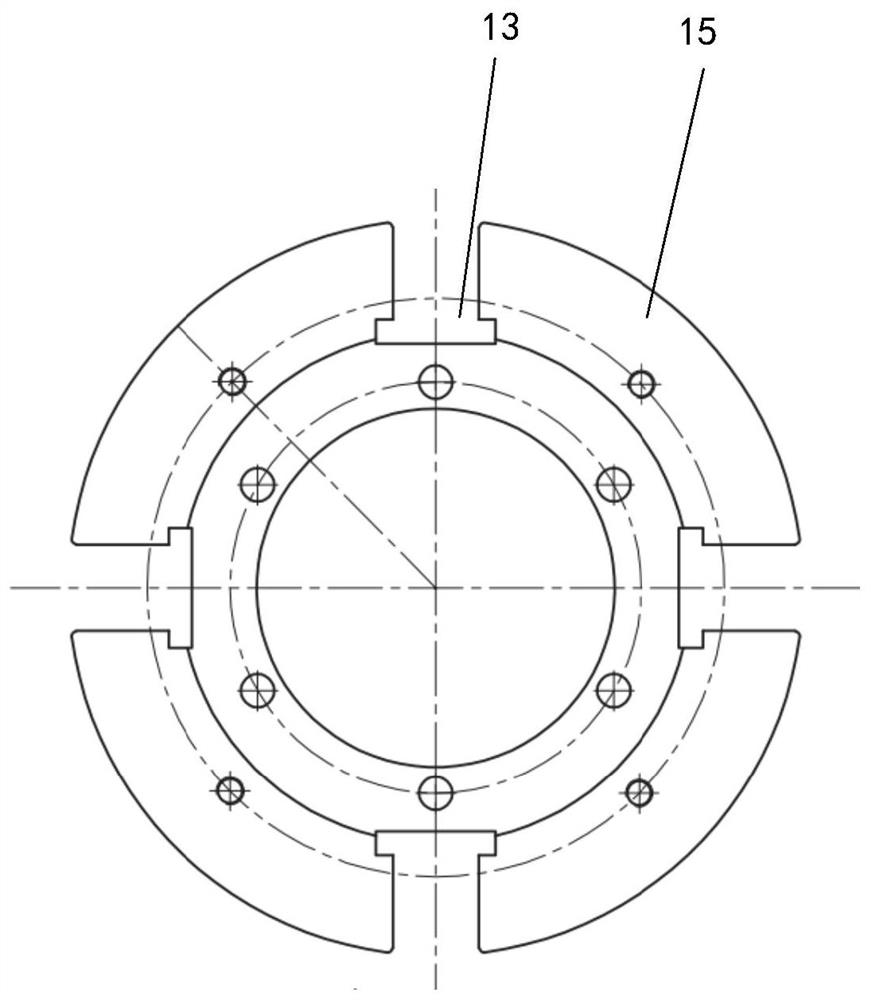
[0031] Please refer to Figure 1 to Figure 4 , figure 1 A cross-sectional view of a wire breaking device of a glass fiber wire drawing machine provided by a specific embodiment of the present inv...


PUM


Abstract

The invention discloses a glass fiber wire drawing machine and a wire breaking device. The wire breaking device comprises a wire cutting ring and at least one wire cutting block fixed on the outer periphery of the wire cutting ring in the circumferential direction to cut the glass fiber. The wire block is conducive to fast wire cutting; the outer circumference of the wire cutting ring has a circular groove for glass fiber winding and a conical groove whose small diameter end is adjacent to the circular groove to guide the glass fiber to be wound to the head. The setting of the conical groove can be adjusted. The glass fiber can be wound quickly, avoiding excessive winding of the glass fiber in the annular groove, which is conducive to reducing the amount of waste wire; all cutting blocks are located between the annular groove and the conical groove, and the outer circumference of the cutting ring has several axially extending And through the broken wire groove of the annular groove and the conical groove, the broken wire groove is used to cut the glass fiber. The glass fiber is cut by two ways of cutting wire block and wire breaking groove, so as to avoid excessive entanglement of glass fiber in the cutting ring, avoid wasting glass fiber, reduce the amount of waste wire, and help reduce production cost.

Description

technical field [0001] The invention relates to the technical field of glass production, in particular to a glass fiber drawing machine and a wire breaking device thereof. Background technique [0002] Glass fiber production has developed into an independent industrial system and has become a material with unique functions in the modern non-metallic material family. Products containing glass fiber can play a role in mechanical, electrical, optical, corrosion resistance, heat insulation and sound absorption. With unique performance, its application fields have spread to various sectors of the national economy such as electronics, electrical appliances, transportation, construction, aviation, aerospace, environmental protection and national defense and military industries. [0003] When making glass fiber, it is firstly made by weighing and mixing various mineral raw materials such as pyrophyllite, quartz sand, limestone, dolomite, borosite, borosite, fluorite, white piolite, ...

Claims


Application Information

Patent Timeline
Patent Type & Authority Patents(China)
IPC IPC(8): C03B37/08C03B37/16C03B37/022
CPCC03B37/08C03B37/16C03B37/022Y02P40/57
Inventor 王国龙蔡兆帅陈磊徐刚谭海军张学斌
Owner CHONGQING POLYCOMP INT
Learn More