Energy-saving system of hot-blast heater for drying tea leaves and using method

An energy-saving system and hot blast stove technology, applied in tea drying, drying, dryer and other directions, can solve the problems of increasing energy consumption, heat energy loss, etc. Effect

Pending Publication Date: 2020-09-11
湖北华宜智能科技有限公司
View PDF0 Cites 2 Cited by
  • Summary
  • Abstract
  • Description
  • Claims
  • Application Information

AI Technical Summary

Problems solved by technology

[0002] In the process of tea processing, there is a drying process. Currently, hot air drying is commonly used. In the hot air drying process, coal-fired hot air stoves are mainly used to heat the air by burning coal and then transport it to the dryer for drying. Dry, and the combustion furnace will produce a large amount of hot exhaust gas during the combustion process. At present, the exhaust gas is directly discharged after simple environmental protection treatment. The above method causes a large loss of heat energy and increases energy consumption.

Method used


Image

  • Energy-saving system of hot-blast heater for drying tea leaves and using method
  • Energy-saving system of hot-blast heater for drying tea leaves and using method

Examples


Embodiment 1

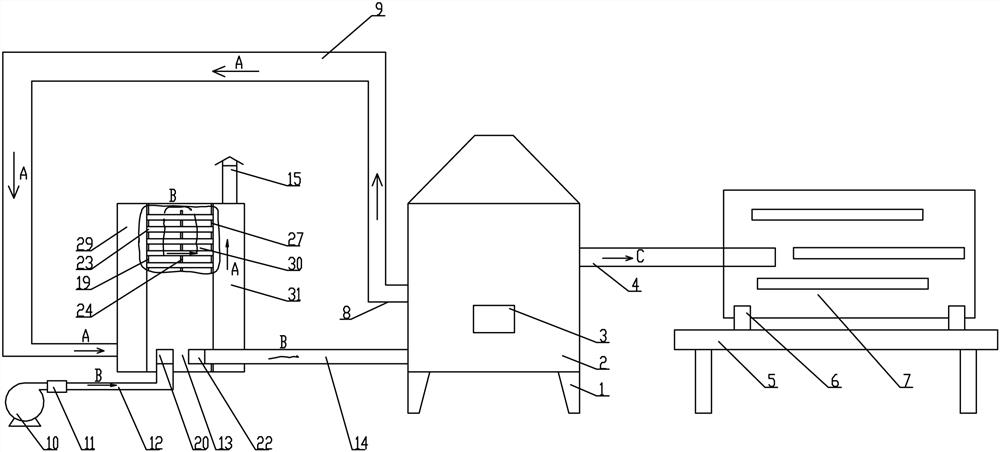
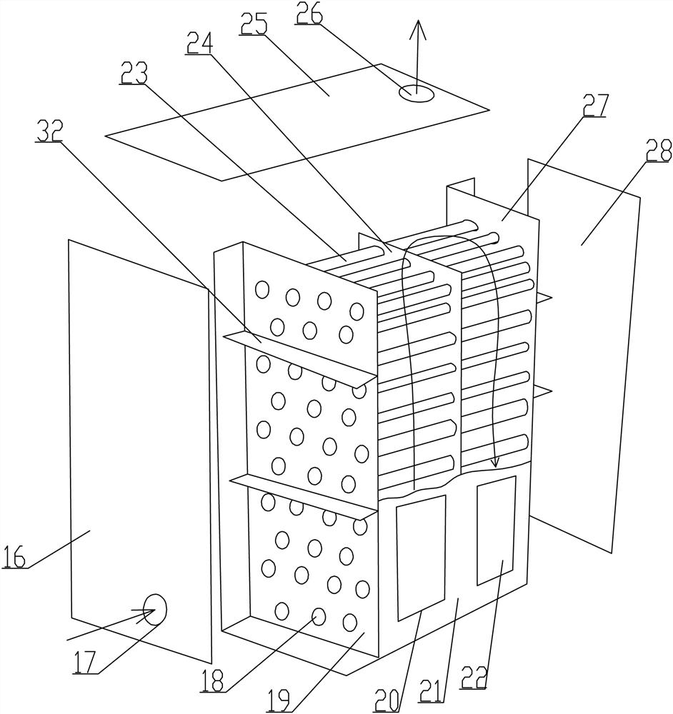
[0035] see Figure 1-2 , an energy-saving system for tea drying hot air stove, which includes a combustion furnace 2, the top of the combustion furnace 2 is provided with a flue gas outlet 8, and the flue gas outlet 8 passes through the flue gas return pipe 9 and the flue gas of the waste heat exchange box 13 The inlet 17 is connected, the top of the other side of the waste heat exchange box 13 is equipped with a smoke exhaust pipe 15, the bottom side of the front side wall of the waste heat exchange box 13 is installed with an air inlet pipe 12, and the other side of the air inlet pipe 12 is A blower 10 is installed at one end, and an air outlet pipe 14 is installed on the other side of the bottom of the front side wall of the waste heat exchange box 13, and the air outlet pipe 14 communicates with the air supply port of the combustion furnace 2, and The hot air outlet is connected to the chain plate dryer 7 through the hot air drying pipe 4 . This energy-saving system great...

Embodiment 2

[0046] The method for using the energy-saving system of the tea drying hot air stove includes the following steps:

[0047] Step 1: Connect the combustion furnace 2 and the waste heat exchange box 13 through the flue gas return pipe 9;

[0048] Step 2: Connect the combustion furnace 2 and the chain plate dryer 7 through the hot air drying pipe 4;

[0049] Step 3: Connect the waste heat exchange box 13 and the combustion furnace 2 through the air outlet pipe 14;

[0050] Step 4: Connect the blower 10 with the waste heat exchange box 13 through the air inlet pipe 12;

[0051] Step 5: Add fuel to the interior of the combustion furnace 2, and start the blower 10 to pass air at normal temperature into the preheating cavity 30 of the waste heat exchange box 13. At this time, the air will enter the air outlet pipe 14 from the air outlet 22 after passing through the turbulence , and then enter the inside of the combustion furnace 2 through the air outlet pipe 14, and discharge from ...


PUM


Abstract

The invention provides an energy-saving system of a hot-blast heater for drying tea leaves and a using method. A smoke outlet is formed in the top of a combustion furnace, and is connected with a smoke inlet of a waste heat exchange box through a smoke return pipe, a smoke discharge pipe is installed at the top of the other side of the waste heat exchange box, an air inlet pipe is installed at oneside of the bottom of the front side wall of the waste heat exchange box, an air blower is installed at the other end of the air inlet pipe, an air outlet pipe is installed at the other side of the bottom of the front side wall of the waste heat exchange box, and communicates with an air supply port of the combustion furnace, and a hot air discharge port of the combustion furnace is connected with a chain plate dryer through a hot air drying pipe. According to the energy-saving system, by repeatedly using tail gas generated in the combustion furnace, the utilization rate of energy is greatlyincreased, and energy consumption is effectively lowered.

Description

technical field [0001] The invention belongs to the field of tea processing devices, and in particular relates to an energy-saving system and a use method of a hot air stove for drying tea. Background technique [0002] In the process of tea processing, there is a drying process. Currently, hot air drying is commonly used. In the hot air drying process, coal-fired hot air stoves are mainly used to heat the air by burning coal and then transport it to the dryer for drying. Dry, and the combustion furnace will produce a large amount of hot exhaust gas during the combustion process. At present, the exhaust gas is directly discharged after simple environmental protection treatment. The above-mentioned method causes a large loss of heat energy and increases energy consumption. Contents of the invention [0003] In order to solve the above technical problems, the present invention provides an energy-saving system for tea drying hot air stoves. This energy-saving system recycles ...

Claims


Application Information

Patent Timeline
IPC IPC(8): F26B21/00F24H3/02F24H9/00A23F3/06
CPCF26B21/001F26B21/004F24H3/027F24H9/0052F24H9/0084A23F3/06F26B2200/20
Inventor 王涛黄孝波
Owner 湖北华宜智能科技有限公司
Why Eureka
Try Eureka