
Novel experimental device for simulating debris flow evolution process under complex conditions

An experimental device and debris flow technology, applied in the field of geotechnical engineering and mountain disasters, can solve problems such as the danger of dumping, the water content of debris flow, the coupling effect of channel angle, curve angle cross-section changes, and the single consideration of the situation. Human and material resources, a wide range of experimental needs, and the effect of improving efficiency

Inactive Publication Date: 2020-09-11
KUNMING PROSPECTING DESIGN INST OF CHINA NONFERROUS METALS IND
View PDF18 Cites 8 Cited by
  • Summary
  • Abstract
  • Description
  • Claims
  • Application Information

AI Technical Summary

Problems solved by technology

As a key part of the boundary conditions, the slope of the trench has an important impact on the evolution characteristics of debris flow. Most of the existing experimental devices are fixed and invariable slope models. It is difficult to achieve quick and precise slope changes during the slope change process, and there is even a danger of tipping over when the slope is too high
In addition, the existing experimental devices still have curves with fixed angles, and the consideration is single; the parameters of debris flow evolution are mostly focused on the monitoring of debris flow velocity and impact force, and the monitoring of debris flow deposition characteristics is often ignored. Research on the fragmentation and splitting of the erosion and deposition process; the research on the coupling effect of debris flow moisture content, channel angle, bend angle, and cross-section changes in the entire evolution process of debris flow involves few issues

Method used


Image

  • Novel experimental device for simulating debris flow evolution process under complex conditions
  • Novel experimental device for simulating debris flow evolution process under complex conditions
  • Novel experimental device for simulating debris flow evolution process under complex conditions

Examples


Embodiment 1

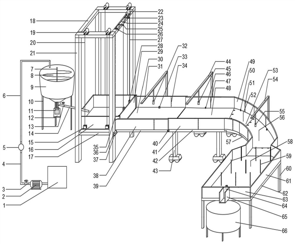
[0034] Embodiment 1: as Figures 1 to 8 As shown, a new experimental device for simulating the evolution process of debris flow under complex conditions, including debris flow slurry preparation device, support device, debris flow slurry holding and lifting device, trench device, and sediment recovery device;

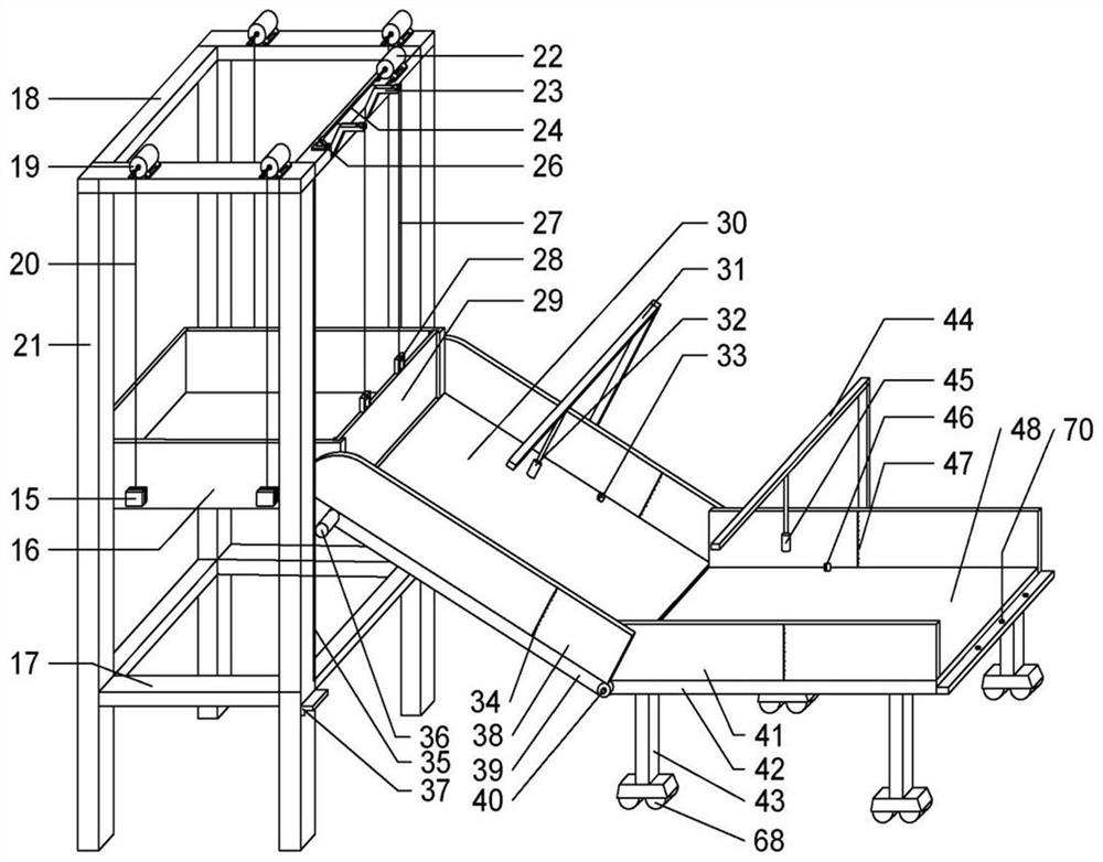
[0035] The slurry outlet of the described mud-rock flow slurry preparation device is positioned at the top of the mud-rock flow slurry holding and lifting device containing the debris flow tank 16. The front end of the groove device is connected, and the end of the groove device is connected with the silt recovery device; the groove device includes a slope-changing groove 30, a horizontal sliding groove 48, and a curved groove device 53 connected in sequence from front to back.

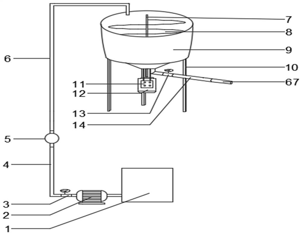
[0036] Further, the debris flow slurry preparation device includes a water tank 1, a water pump 2, a water supply valve 3, a water pipe I4, an electromagnetic flowmeter 5, a water pipe II6, a m...


PUM


Abstract

The invention relates to a novel experimental device for simulating a debris flow evolution process under complex conditions, and belongs to the technical field of geotechnical engineering and mountain disasters. The experimental device comprises a debris flow slurry preparation device, a supporting device, a debris flow slurry containing and lifting device, a groove device and a silting recoverydevice. The debris flow slurry preparation device can be used for preparing debris flow slurries with different water contents; the debris flow slurry containing and lifting device is used for containing, lifting and releasing debris flows, the groove device can simulate the working conditions of different channel gradients and different bend angles, the silting recovery device can simulate the scouring and silting process of the debris flow, and a water-sand separator can separate and recycle water and sand after an experiment is finished. The evolution process of debris flow slurries with different water contents under the conditions of different channel gradients and different bend angles can be completed through cooperation of all the devices, and collection of parameters such as impact, movement and sedimentation of debris flows is monitored and recorded through manual and automatic equipment.

Description

technical field [0001] The invention relates to a novel experimental device for simulating the evolution process of debris flow under complex conditions, which is mainly used for experimental research on the evolution characteristics of channel debris flow, tailings dam or earth-rock dam failure type debris flow, and belongs to the technical field of geotechnical engineering and mountain disasters. Background technique [0002] Debris flow is a sudden geological disaster that may occur in almost all mountainous areas in the world, and is one of the most serious natural disasters in mountainous areas, covering more than 50 countries around the world. my country is a mountainous country with a vast area of ​​mountains, and most of them are in the monsoon climate zone. It is one of the countries that suffer the most serious damage from mudslides. The destructiveness of debris flow is manifested in the huge impact force and large-scale silting during its movement. It can destroy...

Claims


Application Information

Patent Timeline
IPC IPC(8): G01N33/24G01M10/00
CPCG01M10/00G01N33/24
Inventor 刘文连眭素刚胡航王光进樊亚红
Owner KUNMING PROSPECTING DESIGN INST OF CHINA NONFERROUS METALS IND
Features
  • Generate Ideas
  • Intellectual Property
  • Life Sciences
  • Materials
  • Tech Scout
  • Unparalleled Data Quality
  • Higher Quality Content
  • 60% Fewer Hallucinations
Learn More