Vehicle body front bottom plate cross beam and bottom plate longitudinal beam cross-shaped structure and welding process

A welding process and front floor technology, applied in welding equipment, substructure, superstructure, etc., can solve problems such as collision safety risks, achieve the effects of increasing force transmission paths for side collisions, improving collision safety factors, and improving side collision performance

Pending Publication Date: 2020-09-15
ZHEJIANG UFO AUTOMOBILE MFG CO LTD +1
View PDF0 Cites 0 Cited by
  • Summary
  • Abstract
  • Description
  • Claims
  • Application Information

AI Technical Summary

Problems solved by technology

[0005] The invention provides a cross-shaped structure and welding process of the front floor beam and the floor longitudinal beam of the vehicle body. Under the existing layout space, the design space of the vehicle body structure is fully considered, and the front floor beam connecting beam is added at the front of the vehicle body to connect to the longitudinal beam of the vehicle body. Beams, and through the front floor beam joints and longitudinal beams to form a stable and reliable cross-shaped structure, so that in the event of a frontal collision or a side collision, the collision force can be transmitted laterally and forwardly, solving the collision safety risk problem of the original single longitudinal beam structure

Method used


Image

  • Vehicle body front bottom plate cross beam and bottom plate longitudinal beam cross-shaped structure and welding process
  • Vehicle body front bottom plate cross beam and bottom plate longitudinal beam cross-shaped structure and welding process
  • Vehicle body front bottom plate cross beam and bottom plate longitudinal beam cross-shaped structure and welding process

Examples


Embodiment 1

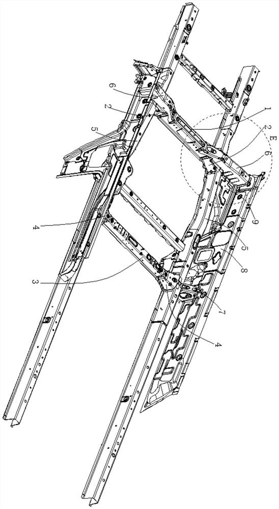
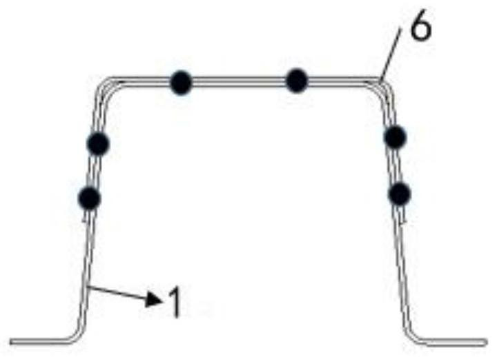
[0057] The cross-shaped structure of the front floor beam and the floor longitudinal beam of the vehicle body also includes a front floor beam connecting beam 6, a rear floor beam external joint 7, a threshold beam 8 and a threshold pedal 9, and the front floor beam connecting beam 6 is arranged on the front floor beam 1 below and extending laterally outward, the front floor beam connecting beam 6 is welded to the front floor beam 1, the front floor beam joint 2 and the longitudinal beam 5 respectively, and the rear floor beam outer joint 7 is located in the outward extension direction of the rear floor beam 3 , and welded with the longitudinal beam 5, the front end of the threshold beam 8 is welded to the end of the front floor beam connecting beam 6, the rear end of the threshold beam 8 is welded to the outer joint 7 of the rear floor beam, and the threshold pedal 9 is respectively connected to the lower end of the longitudinal beam 5 , The lower end of the front floor beam c...

Embodiment 2

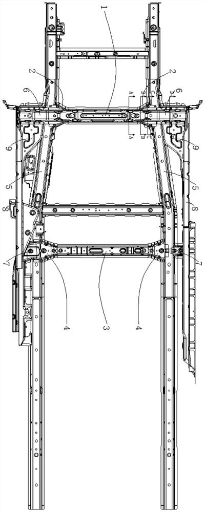
[0060] In the force transmission process of the frontal collision, the collision force is transmitted backward along the front longitudinal beam to the position of the cross structure, which can decompose the collision force into three directions, and a part of the force is transmitted to the opposite side longitudinal beam 5 and Threshold beam 8, part of the force is transmitted to the side sill beam 8 through the front floor beam connecting beam 6, and part of the force is transmitted backward along the longitudinal beam 5; when a frontal collision occurs, whether it is an offset collision or a frontal collision, the The entire lower body frame plays the role of overall bearing and stress, and the cross-shaped structure is also conducive to the transmission of the front impact force along the longitudinal beam 5 through the cross-shaped structure with high rigidity and high strength through the front floor beam 1 and the front floor beam connecting beam 6 To both sides of the...

Embodiment 3

[0062] When a side collision occurs, since the front floor beam 1 and the left and right front floor beam connecting plates traverse the entire vehicle body, part of the side collision force can be carried and transmitted horizontally, and part of the collision force is transmitted forward and backward through the longitudinal beam 5. Bearing and transmitting force, further improving the side impact effect, the transversely penetrating front floor beam connecting beam 6 is welded with the front floor beam 1, front floor beam joint 2 and longitudinal beam 5 to form a cross-shaped structure with high rigidity and strength, and the side impact force Impact on the sill beam 8, carried by the front floor crossbeam joint 2, and transmitted to the front floor crossbeam 1 and the longitudinal beam 5 through the cross-shaped structure, increasing the side impact force transmission path, which is conducive to the front and back transmission of the side impact force through the longitudina...


PUM


Abstract

The invention discloses a Vehicle body front bottom plate cross beam and bottom plate longitudinal beam cross-shaped structure. The structure comprises a front bottom plate cross beam, a front bottomplate cross beam joint, a rear bottom plate cross beam, a rear bottom plate cross beam joint and a longitudinal beam; the structure further comprises a front bottom plate cross beam connecting beam, arear bottom plate cross beam outer joint, a threshold beam and a threshold pedal; the front bottom plate cross beam connecting beam is arranged below the front bottom plate cross beam; the front bottom plate cross beam connecting beam is welded with the front bottom plate cross beam, the front bottom plate cross beam joint and the longitudinal beam; the rear bottom plate cross beam outer joint iswelded with the longitudinal beam; the front end of the threshold beam is welded with the end part of the front bottom plate beam connecting beam; the rear end of the threshold beam is welded with the rear bottom plate cross beam outer joint; the threshold pedal is welded with the lower end of the longitudinal beam, the lower end of the front bottom plate cross beam connecting beam and the lowerend of the threshold beam; the front bottom plate cross beam connecting beam stretches across the longitudinal beam to form a stable and reliable cross-shaped structure, so that when front collision and side collision happen, collision force can be transmitted laterally and forwardly, and the problem of collision safety risks of an original single longitudinal beam structure is solved.

Description

technical field [0001] The invention belongs to the technical field of automobile body structures, in particular, the invention relates to a cross-shaped structure and a welding process of a front floor beam and a floor longitudinal beam of a vehicle body. Background technique [0002] In the frame design of the lower structure of most existing automobile bodies, the front longitudinal beam in the engine compartment extends backward, fits the front fender backward, and is connected with the longitudinal beam as a whole. At the same time, at the rear end of the front longitudinal beam, a diagonally braced beam structure is added on the left and right sides to realize the connection with the sill beam and the middle channel longitudinal beam respectively, so as to realize the decomposition of the front force transmission of the vehicle body into three paths, improve the force transmission performance of the front collision, and effectively increase the collision force transmis...

Claims


Application Information

Patent Timeline
IPC IPC(8): B62D21/02B62D25/20B23K31/02B23K37/00
CPCB23K31/02B23K37/00B62D21/02B62D25/2009B23K2101/006
Inventor 王力陈文仙万中留朱方强
Owner ZHEJIANG UFO AUTOMOBILE MFG CO LTD
Why Eureka
Try Eureka