
High-speed railway safety zone intrusion alarm device and method based on infrared images

A high-speed railway, infrared image technology, applied in image enhancement, image analysis, image communication, etc., can solve the problems of delay, intrusion alarm system recognition accuracy decline, and inability to obtain clear monitoring images.

Pending Publication Date: 2020-09-15
SHANGHAI UNIV OF ENG SCI
View PDF0 Cites 1 Cited by
  • Summary
  • Abstract
  • Description
  • Claims
  • Application Information

AI Technical Summary

Problems solved by technology

However, video surveillance devices for real-time monitoring of safe areas are generally based on visible light imaging sensors, which makes it impossible for such video surveillance devices to obtain clear surveillance images under conditions such as poor lighting effects and poor weather conditions, making intrusion alarm systems The recognition accuracy of the
On the other hand, in order to complete the image recognition process of the monitoring screen of the high-speed railway safety zone, the monitoring device must transmit the monitoring data to the terminal processing platform of the designated station monitoring center after collecting the monitoring images of the high-speed railway safety zone. Transmission data loss or delay may occur, which makes intrusion detection take more time

Method used


Image

  • High-speed railway safety zone intrusion alarm device and method based on infrared images
  • High-speed railway safety zone intrusion alarm device and method based on infrared images
  • High-speed railway safety zone intrusion alarm device and method based on infrared images

Examples


Embodiment Construction

[0096] The present invention will be further described below in combination with specific embodiments. It should be understood that these examples are only used to illustrate the present invention and are not intended to limit the scope of the present invention. In addition, it should be understood that after reading the teachings of the present invention, those skilled in the art can make various changes or modifications to the present invention, and these equivalent forms also fall within the scope defined by the appended claims of the present application.

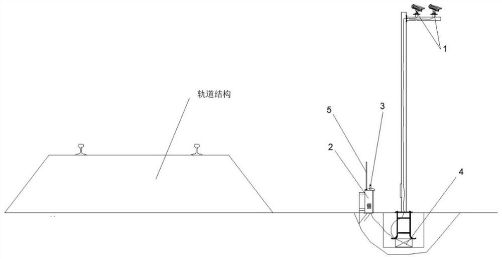
[0097] A high-speed railway safety zone intrusion alarm device based on infrared images, such as figure 1 As shown, it includes a data collection module 1, a ground analysis module 2, an early warning module 3, a power supply module 4, a remote communication module 5 and a terminal monitoring platform;

[0098] The data acquisition module 1 and the ground analysis module 2 are connected through a data transmission line,...


PUM


Abstract

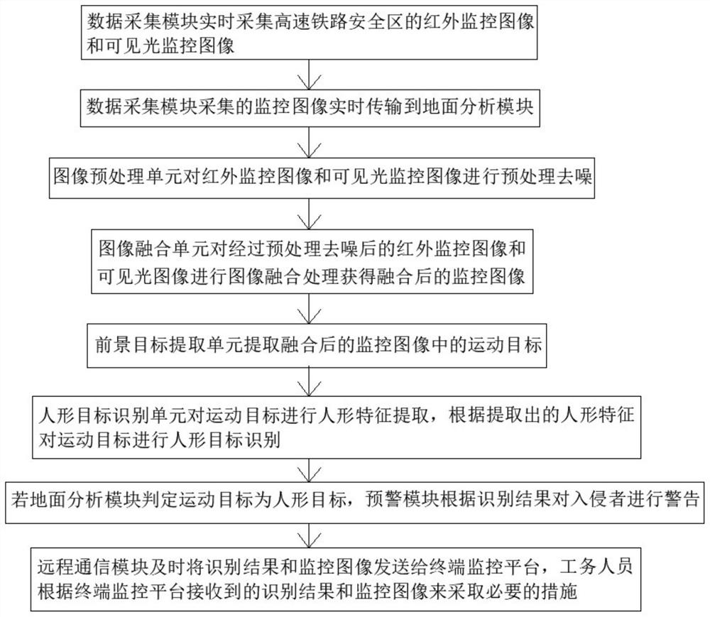
The invention relates to a high-speed railway safety zone intrusion alarm device and method based on infrared images. The alarm device comprises a data acquisition module, a ground analysis module, anearly warning module, a remote communication module, a power supply module and a terminal monitoring platform. The data acquisition module is used for acquiring a monitoring image of a high-speed railway safety zone in real time; the ground analysis module is used for analyzing and processing the acquired monitoring image; the early warning module is used for sending out a warning signal; the remote communication module is used for transmitting an identification result and the monitoring image; the power module is used for supplying power to the whole device; and the terminal monitoring platform is used for checking the identification result and a field image by a worker. The intrusion alarm device can autonomously perform image processing, human shape recognition and result feedback, adverse effects of factors such as illumination conditions, weather conditions and the like on the intrusion alarm device are avoided, and working efficiency and accuracy of the intrusion alarm device are improved.

Description

technical field [0001] The invention belongs to the technical field of high-speed railway safety zone state monitoring, and relates to an infrared image-based high-speed railway safety zone intrusion alarm device and method. Background technique [0002] The overall goal of the "13th Five-Year Plan" railway plan is to reach 150,000 kilometers of railways by 2020, and 30,000 kilometers of high-speed railways. Railway investment is planned to reach 3.8 trillion yuan. With the development of China's high-speed railways, the mileage of high-speed railways has become longer and longer, which has greatly promoted economic development and the efficiency of personnel exchanges in various places. However, it also brings a lot of potential safety hazards. The railway facilities are destroyed and the situation of directly passing the railway line regardless of the protective net occurs from time to time. This has caused great damage to the safe production of the railway, not only caus...

Claims


Application Information

Patent Timeline
IPC IPC(8): G08B13/196H04N7/18G06T7/194G06T5/00G06K9/62G06K9/46G06K9/00
CPCG08B13/196G08B13/19602H04N7/181G08B13/19665G06T7/194G06T2207/20081G06T2207/20084G06V20/52G06V10/56G06F18/251G06T5/70
Inventor 李再帏路宏遥何越磊孟晓亮马跃坤
Owner SHANGHAI UNIV OF ENG SCI
Learn More