Hardware punching iron filings adsorption equipment based on magnetic attraction principle

A technology for adsorption equipment and hardware, applied in metal processing equipment, drilling/drilling equipment, parts of boring machine/drilling machine, etc., can solve the problems of increasing work intensity, polluting the environment, iron filings splashing, etc., to avoid iron filings splash effect

Active Publication Date: 2020-09-18
深圳市兴明源机械有限公司
View PDF6 Cites 9 Cited by
  • Summary
  • Abstract
  • Description
  • Claims
  • Application Information

AI Technical Summary

Problems solved by technology

[0003] We all need to punch holes when we use hardware in our daily life, especially in the mass production process of some large factories, but in the production process, a lot of waste and slag will be generated when punching holes and some smaller cutting workpieces, These will fall under the cutting platform, which will bring a lot of inconvenience to normal production activities, increase the work intensity and reduce work efficiency, and the accumulation of waste and slag in the cutting machine will pollute the environment and affect the appearance; Iron filings often splash and accumulate on the bottom plate of cutting equipment when punching holes. Since iron filings have high recycling value, it is often necessary to recycle the iron filings generated during drilling. This will undoubtedly greatly increase the labor intensity
[0004] Therefore, we proposed a hardware punching iron chip adsorption device based on the principle of magnetic attraction. Through the built-in magnetic attraction component, the waste generated when the hardware is punched is collected, which avoids the traditional hardware punching equipment, and does not It has the function of recycling grinding waste; it solves the problem that traditional metal punching equipment often has iron filings splashing and then piled up on the bottom plate of the cutting equipment

Method used


Image

  • Hardware punching iron filings adsorption equipment based on magnetic attraction principle
  • Hardware punching iron filings adsorption equipment based on magnetic attraction principle
  • Hardware punching iron filings adsorption equipment based on magnetic attraction principle

Examples


Embodiment Construction

[0028] The following will clearly and completely describe the technical solutions in the embodiments of the present invention with reference to the accompanying drawings in the embodiments of the present invention. Obviously, the described embodiments are only some, not all, embodiments of the present invention. Based on the embodiments of the present invention, all other embodiments obtained by persons of ordinary skill in the art without making creative efforts belong to the protection scope of the present invention.

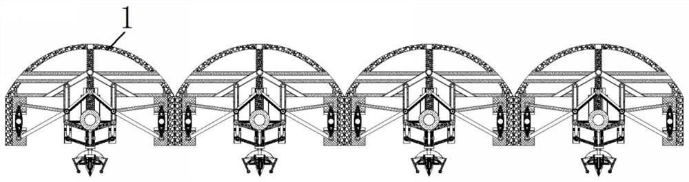
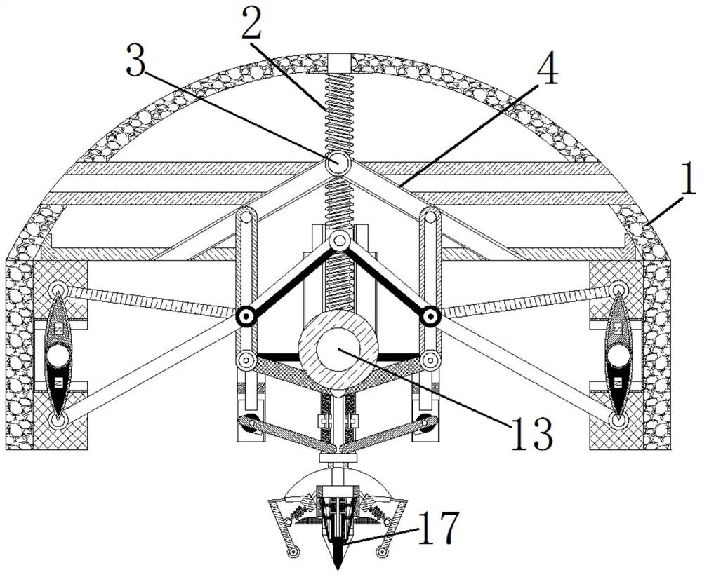
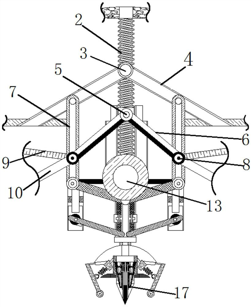
[0029] see Figure 1-8 , a hardware punching and iron filings adsorption device based on the principle of magnetic attraction, including a device main body 1, a driving screw 2 is arranged inside the device main body 1, a movable shaft 3 is movably connected to the lower part of the driving screw 2, and the outer side of the movable shaft 3 A shaft rod 4 is movably connected, and the outer thread of the drive screw 2 is connected with a bearing 5, and the oute...


PUM


Abstract

The invention relates to the technical field of hardware castings, and discloses hardware punching iron filings adsorption equipment based on the magnetic attraction principle. The hardware punching iron filings adsorption equipment comprises an equipment main body. A driving screw is arranged inside the equipment main body, and a movable rotating shaft is movably connected under the driving screw. The outer side of a bearing is movably connected with one end of a connecting rod. The other end of the connecting rod is movably connected with a sliding rod. A sliding block is arranged inside thesliding rod. The outer side of the sliding block is movably connected with a first magnetic rod and a second magnetic rod. The outer sides of the first magnetic rod and the second magnetic rod are movably connected with magnetic blocks. The inner sides of the magnetic blocks clamp an electromagnet. An abutment block is threadedly connected with the bottom end of the driving screw. According to the hardware punching iron filings adsorption equipment based on the magnetic attraction principle, through arranging a baffle on the outside of a punching bit, iron filings are avoided from being splashed, and the problem that staff is prone to being hurt due to the fact that traditional hardware punching equipment often has iron filings splashing is solved.

Description

technical field [0001] The invention relates to the technical field of metal castings, in particular to a hardware perforated iron chip adsorption device based on the principle of magnetic attraction. Background technique [0002] Hardware: Traditional hardware products, also known as hardware, refer to five metals including gold, silver, copper, iron and tin. After manual processing, they can be made into works of art or metal devices such as knives and swords. Hardware in modern society is more extensive, such as Hardware tools, hardware parts, daily hardware, construction hardware and security supplies, etc. [0003] We all need to punch holes when we use hardware in our daily life, especially in the mass production process of some large factories, but in the production process, a lot of waste and slag will be generated when punching holes and some smaller cutting workpieces, These will fall under the cutting platform, which will bring a lot of inconvenience to normal pr...

Claims


Application Information

Patent Timeline
Patent Type & Authority Applications(China)
IPC IPC(8): B23B39/00B23B47/18B23Q11/00B23Q11/08
CPCB23B39/00B23Q11/0064B23Q11/08B23Q5/40
Inventor 王建富
Owner 深圳市兴明源机械有限公司
Why Eureka
Try Eureka