A drilling device for a micro-valve body for a forklift and its production process

A drilling device and micro-valve technology, applied in the driving device, feeding device, boring/drilling and other directions, can solve the problems of low drilling efficiency and complicated drilling process, so as to improve the drilling efficiency and simplify the drilling process. Production process flow, the effect of improving efficiency

Active Publication Date: 2021-09-28
杭州顺钢机械有限公司
View PDF10 Cites 0 Cited by
  • Summary
  • Abstract
  • Description
  • Claims
  • Application Information

AI Technical Summary

Problems solved by technology

[0004] The above-mentioned existing technical solutions have the following defects: the valve body of the above-mentioned forklift micro-motion valve has several connecting holes parallel to each other. In the prior art, the connecting holes on the valve body are usually processed by a drilling machine, and the corresponding The drill bit drills holes on the valve body in turn. If several connecting holes need to be drilled, the drilling machine needs to move up and down several times to drill holes, resulting in low drilling efficiency and complicated drilling process.

Method used


Image

  • A drilling device for a micro-valve body for a forklift and its production process
  • A drilling device for a micro-valve body for a forklift and its production process
  • A drilling device for a micro-valve body for a forklift and its production process

Examples


Embodiment 1

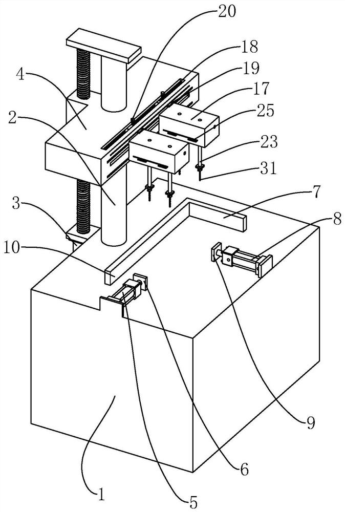
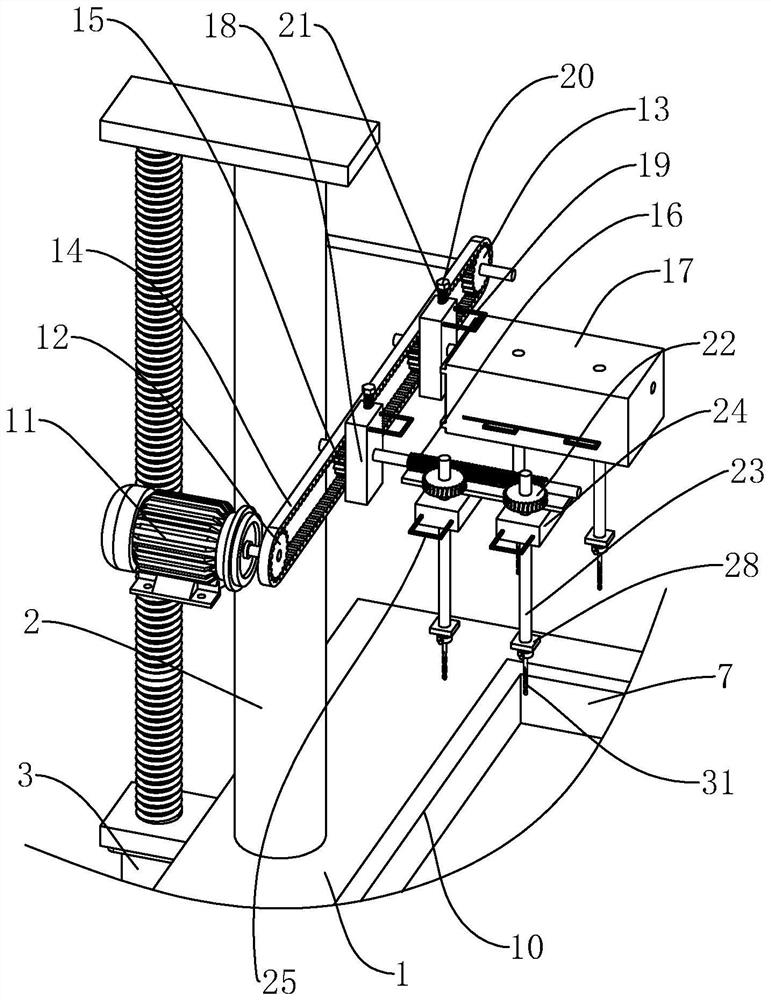
[0044] refer to figure 1 and figure 2 , the invention discloses a drilling device for a micro-valve body for a forklift, which comprises a body 1 which is in a square shape. The body 1 is fixed with a vertical lifting rod 2, and the lifting rod 2 is slidably connected with a horizontal lifting frame 4. The body 1 is fixed with a vertical lifting motor 3, and the output shaft of the lifting motor 3 runs through the lifting frame 4 and It is threadedly connected with lifting frame 4. The operator places the valve body that needs to be drilled on the body 1, starts the lifting motor 3, the lifting motor 3 rotates and then drives the lifting frame 4 to move up and down through the output shaft of the lifting motor 3, and the height of the lifting frame 4 can be adjusted up and down. The lifting frame 4 is fixed with a horizontal driving motor 11, and the side of the lifting frame 4 away from the lifting rod 2 is connected with a drill bit 31. The driving motor 11 rotates to dri...

Embodiment 2

[0056] A production process for a micro-motion valve body for a forklift, comprising the following steps:

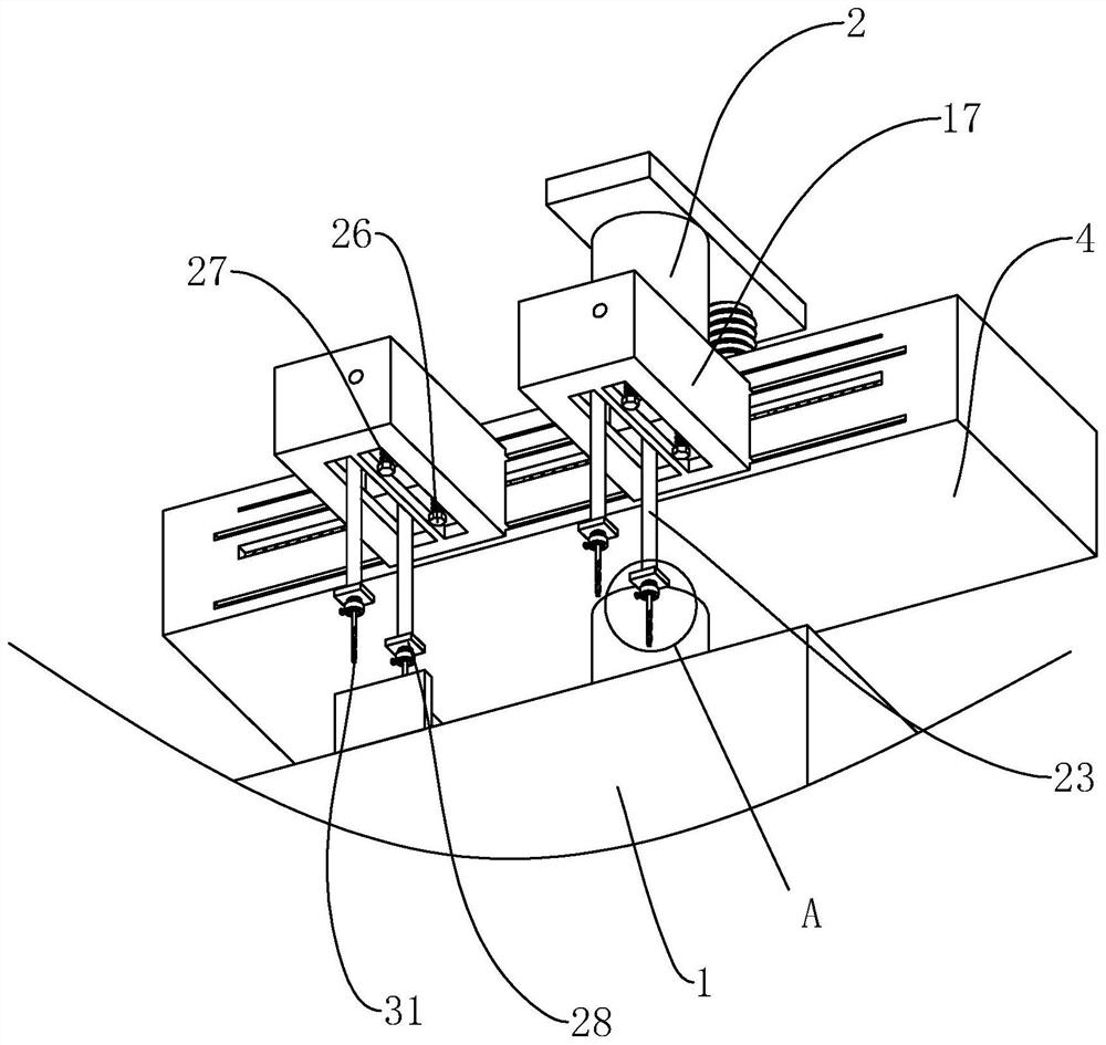
[0057] S1 The operator first places the valve body that needs to be drilled on the body 1, starts the clamping cylinder 1 5 and the clamping cylinder 2 8, and passes through the clamping plate 1 6 and the fixing plate 1 7, the clamping plate 2 9 and the fixing plate Two 10 cooperate with each other, and then clamp and fix the valve body;

[0058] S2 selects the drill bit 31 that is suitable for drilling holes on the valve body, first loosens the fastening ring 30, and then installs the drill bit 31 in the jaw 29, then tightens the fastening ring 30, and then tightens the fixing bolt 32 until the fixing bolt 32 Interfere with the jaws 29 to fix the position of the drill bit 31;

[0059] S3 adjust the distance between the drill bit 31 and the drill bit 31 along the direction of the drive tooth chain 14 according to the specific position of the hole drilled on the valve bo...


PUM


Abstract

The invention relates to a drilling device for a micro-movement valve body for a forklift and its production process, which belongs to the technical field of forklift manufacturing. , the body is fixed with a vertical lifting motor, the lifting frame is provided with a plurality of longitudinal gears connected with the drive motor, the axial position of the longitudinal gear is fixed with a horizontal transmission screw, and the end of the lifting frame away from the driving motor is provided with A plurality of horizontal connecting frames, the transmission screw is placed in the connecting frame and connected to the connecting frame in rotation, a plurality of horizontal gears meshed with the transmission screw are arranged in the connecting frame, and a vertical transmission is fixed on the axis position of the horizontal gear shaft, the end of the transmission shaft far away from the transverse gear is provided with a vertical drill bit, the drive motor is started, and then several drill bits are driven to rotate at the same time, and then multiple drill holes are processed at one time. The present invention has the advantages of improving drilling efficiency and simplifying the production process. Effect.

Description

technical field [0001] The invention relates to the technical field of forklift manufacturing, in particular to a drilling device for a micro-valve body for a forklift and a production process thereof. Background technique [0002] The forklift micro valve is one of the key components in the hydraulic system of the forklift, which is used together with the oil supply pump, control valve and hydraulic clutch. [0003] The existing Chinese patent with the publication number CN103482534A discloses a forklift micro-motion valve, which includes a valve body, a plug, a first O-ring, a second O-ring, and a gasket. The end face of the valve body is provided with a plug hole and a hole slot in sequence from the inside to the outside. The plug is accommodated in the plug hole, and the first O-ring is also accommodated in the plug hole and is located at the bottom of the plug away from the plug hole. on one side of the The gasket is accommodated at the bottom of the plug hole, the si...

Claims


Application Information

Patent Timeline
Patent Type & Authority Patents(China)
IPC IPC(8): B23B39/16B23B41/00B23B47/00B23B47/26B23B47/30B23Q5/10B23Q5/28B23B47/06B23B47/20
CPCB23B39/16B23B41/00B23B47/00B23B47/26B23B47/30B23Q5/10B23Q5/28
Inventor 黄春鸿
Owner 杭州顺钢机械有限公司
Why Eureka
Try Eureka