Slope surface debris flow prevention and treatment engineering structure and slope surface debris flow prevention and treatment method

A technology for prevention and control of engineering and debris flow, applied in drainage structures, waterway systems, buildings, etc., can solve the problems of large amount of engineering investment, difficult prevention and blocking engineering, and high investment cost, achieve low investment quota, reduce the amount of infiltration water, and is not easy. The effect of soil sliding

Active Publication Date: 2020-09-18
王恩厚
View PDF12 Cites 2 Cited by
  • Summary
  • Abstract
  • Description
  • Claims
  • Application Information

AI Technical Summary

Problems solved by technology

Due to the large energy and power of debris flow, it is difficult to resist the general preventive and blocking projects. Most of them use concrete to build embankments. Because there are many areas prone to occurrence, the amount of engineering involved is relatively large, and the investment cost is relatively high.

Method used


Image

  • Slope surface debris flow prevention and treatment engineering structure and slope surface debris flow prevention and treatment method
  • Slope surface debris flow prevention and treatment engineering structure and slope surface debris flow prevention and treatment method
  • Slope surface debris flow prevention and treatment engineering structure and slope surface debris flow prevention and treatment method

Examples


Embodiment 1

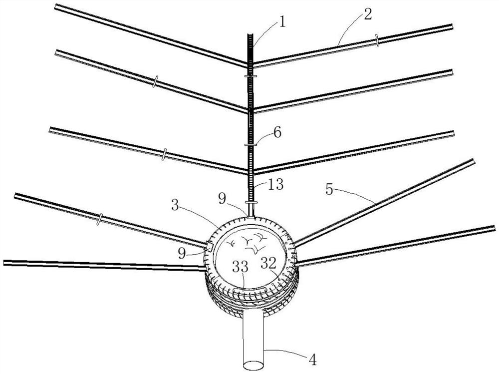
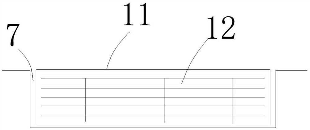
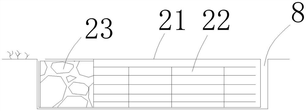
[0058] The slope debris flow prevention and control engineering structure in this embodiment adopts the method of intercepting runoff and diverting the source to reduce the amount of infiltration water in areas prone to debris flow to a certain extent, so as to achieve the purpose of preventing debris flow disasters caused by soil layer sliding, such as figure 1 , figure 2 , image 3 , Figure 4 Shown:

[0059] Basically, a group of the slope debris flow prevention and control engineering structure includes a main diversion zone 1 , at least one first branch diversion zone 2 , a hydrosphere well 3 and a drainage pipe 4 .

[0060] In this slope debris flow prevention engineering structure, the main diversion zone 1 is arranged vertically, and the first diversion zone 2 is arranged obliquely. The first diversion zone 2 can be set in multiples according to the actual situation. It can be set on the left or right side of the main guide belt 1. The main diversion belt 1 is use...


PUM


Abstract

The invention provides a slope surface debris flow prevention and treatment engineering structure and a slope surface debris flow prevention and treatment method, relates to the technical field of debris flow prevention and treatment, and aims to solve the problem about debris flow prevention and treatment from the source. According to the slope surface debris flow prevention and treatment method,the slope surface debris flow prevention and treatment engineering structure is arranged at the slope surface of the upstream of an area with debris flow frequently occurring; a main flow diversion belt is longitudinally arranged; a first branched flow diversion belt is slantly arranged; a water gathering ring well is arranged at the downstream of the main flow diversion belt; a water storage cabin is arranged in the water gathering ring well; the main flow diversion belt and the first branched flow diversion belt are used for intercepting surface layer water flow or runoff and guiding the intercepted water flow to flow in the guiding direction; the downstream end of the main flow diversion belt is connected with the upstream end of the water gathering ring well and communicates with thewater storage cabin; the downstream end of the first branched flow diversion belt is connected with the midsteam section of the main flow diversion belt and realizes confluence; a drain pipe is connected with the downstream end of the water gathering ring well and communicates with the water storage cabin. The slope surface debris flow prevention and treatment engineering structure adopts the runoff interception and source dredging manner, reduces the amount of infiltrating water of a frequent debris flow area to certain degree, and realizes the purpose of avoiding a debris flow disaster through preventing soil layer sliding.

Description

technical field [0001] The invention relates to the technical field of mud-rock flow prevention and control, in particular to an engineering structure for preventing mud-rock flow on a slope surface and a method for preventing mud-rock flow on a slope surface. Background technique [0002] In order to prevent and reduce the loss of debris flow disasters, most of the current prevention and control measures are to build some blocking projects in the downstream ditches in prone areas. Due to the large energy and power of debris flow when it occurs, it is difficult to resist the general preventive and blocking projects. Most of them use concrete to build embankments. Because there are many areas prone to occurrence, the amount of engineering involved is large and the investment cost is high. Even such investment may not be able to radically cure the areas prone to debris flow disasters fundamentally or at the source. [0003] The cause of debris flow is firstly affected by the ...

Claims


Application Information

Patent Timeline
Patent Type & Authority Applications(China)
IPC IPC(8): E03F3/02E03F3/04E03F5/10E03F5/06
CPCE03F3/02E03F3/04E03F3/046E03F5/102E03F5/103E03F5/06Y02A30/60
Inventor 王恩厚
Owner 王恩厚
Why Eureka
Try Eureka