
Material tank transfer device for cosmetic production workshop

A production workshop and transfer device technology, applied in chemical/physical processes, transportation and packaging, chemical instruments and methods, etc., can solve problems affecting the production quality of cosmetics, poor cosmetic preservation effect, and poor material protection effect, etc., to increase Post-processing quality, novel design, ensuring the effect of movement and fixed action

Inactive Publication Date: 2020-09-22
李凯
View PDF1 Cites 0 Cited by
  • Summary
  • Abstract
  • Description
  • Claims
  • Application Information

AI Technical Summary

Problems solved by technology

In the prior art, when transferring the production materials of cosmetics, the transfer tanks containing the cosmetics are usually placed on the cart for transportation. On the one hand, these transfer tanks have poor preservation effect on cosmetics. Long, it will lead to denaturation of materials, which will greatly affect the production quality of cosmetics. On the other hand, the protection effect on materials is not good. When the transfer tank is subjected to external force, some fragile materials will be damaged and cause losses.
[0004] Chinese patent (notification number: CN210555058U) discloses a material transfer tank for cosmetic production workshops, including a base, an outer box, an inner box and a sealing cover. The four corners of the upper surface of the base are respectively fixedly connected with the bottom end of a vertically installed first shock absorber, the top of the first shock absorber is fixedly connected with the bottom surface of the outer box, and the box of the outer box There is a temperature insulation groove in the inner wall. Although this device can ensure the effective transfer of the material tank to a certain extent, in actual operation, the material inside the material tank is always in a static state. Once transferred to the destination, the material inside the material tank Cosmetics are easy to solidify, which seriously affects the efficiency of later production and processing. Therefore, further improvement is needed

Method used


Image

  • Material tank transfer device for cosmetic production workshop
  • Material tank transfer device for cosmetic production workshop
  • Material tank transfer device for cosmetic production workshop

Examples


Embodiment 1

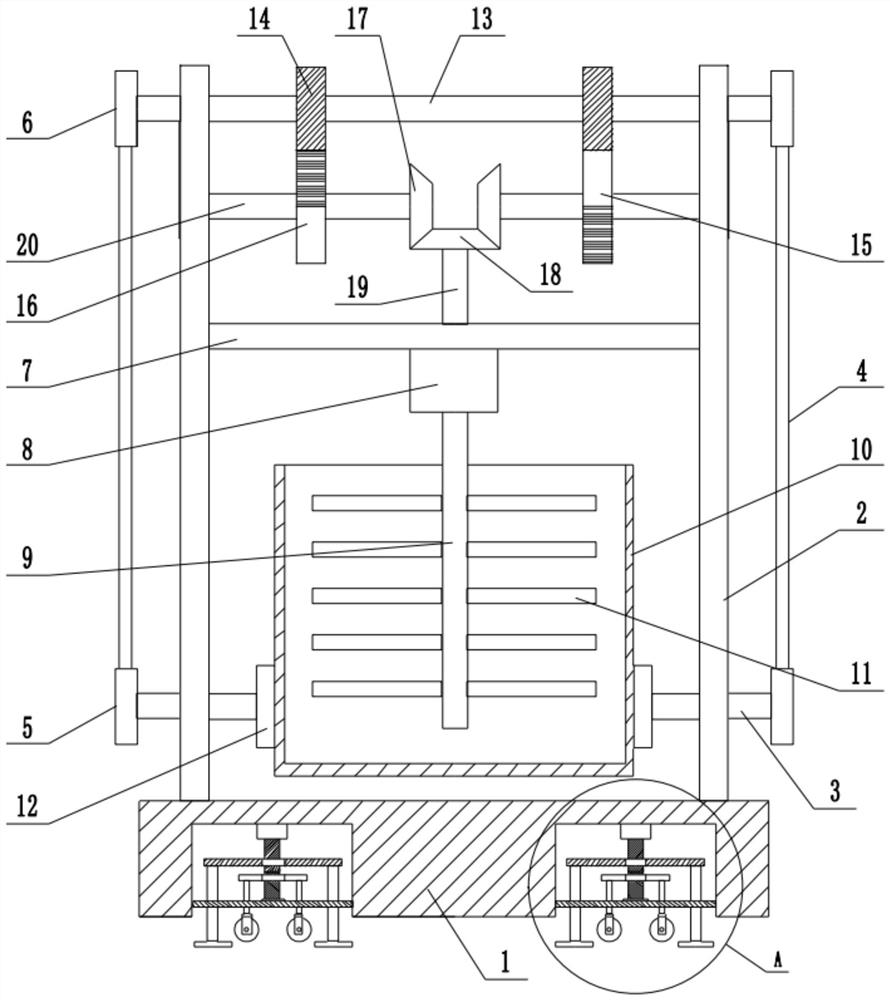
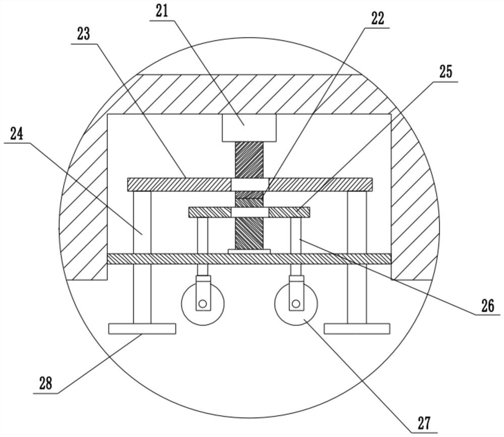
[0028] Referring to the figure, in an embodiment of the present invention, a material tank transfer device for a cosmetics production workshop includes a fixed base 1, a support frame 2 is installed on both sides of the upper end of the fixed base 1, and a fixed plate 7 is installed between the middle parts of the support frame 2 , the middle part of the fixed plate 7 is fixed with a biaxial motor 8, so that the upper output shaft 19 and the lower output shaft 9 can be driven to rotate simultaneously, a rotating shaft 13 is installed between the upper ends of the support frame 2, and a rotating gear 14 is installed in the middle of the two ends of the rotating shaft 13, The lower end of the rotating gear 14 is intermittently meshed with a left gear 16 and a right gear 15, and the outer sides of the left gear 16 and the right gear 15 are provided with a half circle of teeth, thereby ensuring that only one of the left gear 16 and the right gear 15 can be matched with the correspon...

Embodiment 2

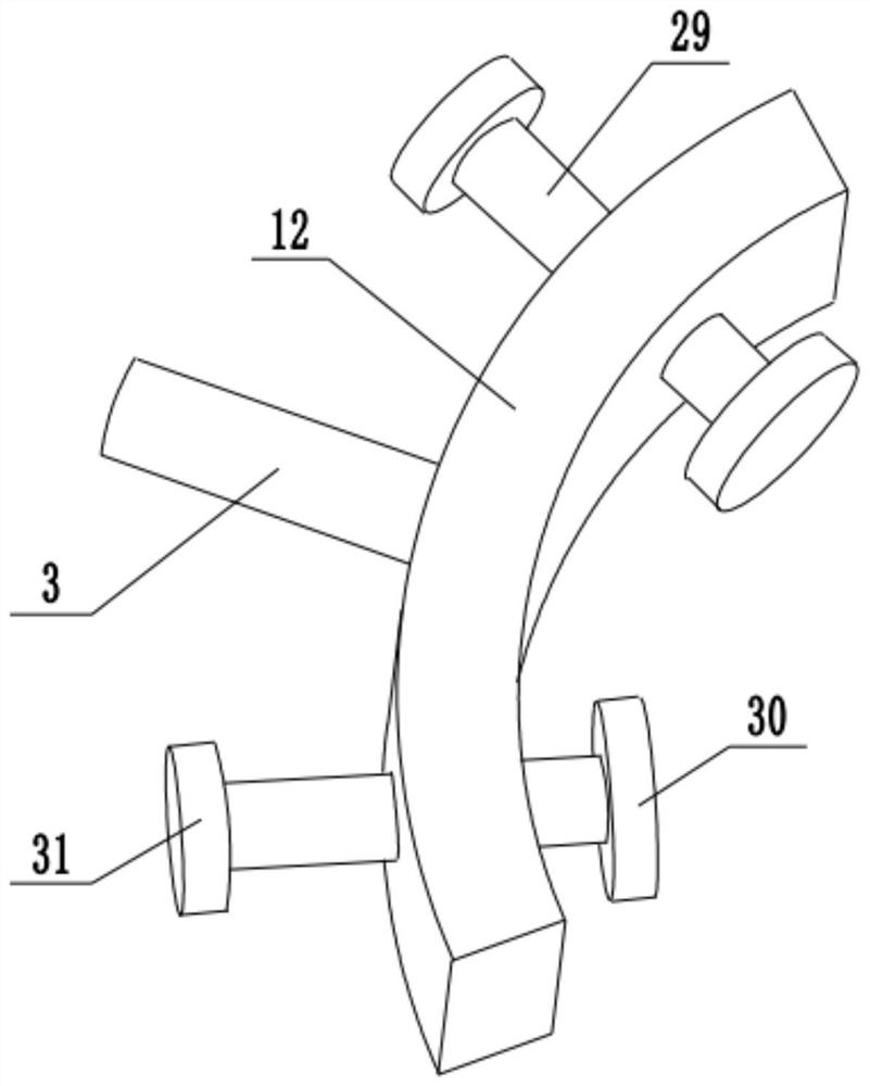
[0031] refer to image 3 , in another embodiment of the present invention, the difference between this embodiment and the above-mentioned embodiment is that a tank body 10 is arranged between the fixed rings 12, threaded columns 29 are respectively installed in the front and rear middle parts of the fixed rings 12, and the threaded columns A clamping block 30 is installed at the inner side of 29, and an adjusting block 31 is installed at the outer end of the threaded column 29. By setting the adjusting block 31, the threaded column 29 is rotated, so that the clamping block 30 clamps and fixes the corresponding tank body 10.

[0032]In the present invention, when working, the material tank that needs to be transferred is placed between the fixed rings 12, and the biaxial motor 8 is started at the same time, so that the biaxial motor 8 drives the output shaft 9 to rotate on the one hand, and the tank body is mixed under the action of the mixing blade 11. The material is stirred....


PUM


Abstract

The invention relates to the technical field of cosmetic production equipment. The invention discloses a material tank transfer device for a cosmetic production workshop. The material tank transfer device comprises a fixed base; support frames are mounted on two sides of the upper end of the fixed base; a rotating shaft is mounted between the upper ends of the support frames; rotating gears are mounted in the middles of two ends of the rotating shaft; the lower ends of the rotating gears are intermittently engaged with a left gear and a right gear; rotating shafts are mounted in the middles ofthe left gear and the right gear; a driven gear is mounted at one end inside each rotating shaft; the lower ends of the driven gears are meshed with a driving gear; the lower end of the driving gearis provided with an upper output shaft of a double-shaft motor, the lower end of the double-shaft motor is provided with a lower output shaft, the two ends of the rotating shaft penetrate through thesupporting frame to be provided with driving belt wheels, the lower ends of the driving belt wheels are connected with driven belt wheels through belts, and the other ends of the driven belt wheels are provided with belt wheel shafts. According to the material tank transfer device, cosmetic raw materials in the material tank are stirred, the swinging effect on the whole material tank is also achieved, solidification of the materials in the material tank is avoided, and the later-period processing quality is greatly improved.

Description

technical field [0001] The invention relates to the technical field of cosmetic production equipment, in particular to a material tank transfer device for a cosmetic production workshop. Background technique [0002] Cosmetics refer to smearing, spraying or other similar methods that are spread on any part of the human body surface, such as skin, hair, nails, lips and teeth, etc., to achieve cleaning, maintenance, beauty, modification and change of appearance, or to correct human body odor, maintain Chemical industrial products or fine chemical products for the purpose of good condition. [0003] In the production workshop of cosmetics, it is often necessary to transfer the production materials of cosmetics and transport the materials to various locations in the workshop. In the prior art, when transferring the production materials of cosmetics, the transfer tanks containing the cosmetics are usually placed on the cart for transportation. On the one hand, these transfer tan...

Claims


Application Information

Patent Timeline
Patent Type & Authority Applications(China)
IPC IPC(8): B01F11/00B01F13/00B01F15/00
CPCB01F31/56B01F31/70B01F33/502B01F33/86B01F35/31B01F35/3204B01F35/332B01F35/43B01F2101/21
Inventor 李凯
Owner 李凯
Learn More