
A combined mold and working method for automatic laying of composite materials

A composite material and combined mold technology, applied in the field of composite material parts manufacturing, can solve the problems of low manufacturing efficiency, easy collision interference, poor manufacturing stability of composite material parts, etc., and achieve high molding efficiency, avoid interference, and high quality consistency Effect

Active Publication Date: 2022-04-12
AVIC BEIJING AERONAUTICAL MFG TECH RES INST
View PDF16 Cites 0 Cited by
  • Summary
  • Abstract
  • Description
  • Claims
  • Application Information

AI Technical Summary

Problems solved by technology

[0005] The invention proposes a combined mold and working method for the composite material automatic laying process. The combined mold is used to solve the problem that the composite material laying mold and equipment are easy to collide and interfere in the manufacture of composite material parts, resulting in stable manufacturing of composite material parts. Technical problems of poor performance and low manufacturing efficiency

Method used


Image

  • A combined mold and working method for automatic laying of composite materials
  • A combined mold and working method for automatic laying of composite materials
  • A combined mold and working method for automatic laying of composite materials

Examples


Embodiment Construction

[0031] Embodiments of the present invention will be further described in detail below in conjunction with the accompanying drawings and examples. The detailed description and accompanying drawings of the following embodiments are used to illustrate the principles of the present invention, but cannot be used to limit the scope of the present invention, that is, the present invention is not limited to the described embodiments, without departing from the spirit of the present invention Any modification, substitution and improvement of parts, components and connection methods are covered under.

[0032] It should be noted that, in the case of no conflict, the embodiments in the present application and the features in the embodiments can be combined with each other.

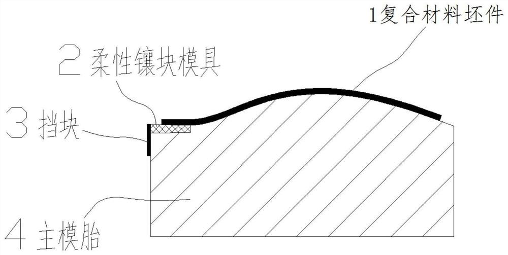
[0033] combine Figure 1 to Figure 5 The specific implementation of this example will be described.

[0034] figure 1 It discloses a schematic diagram of laying a prepreg molding composite material blank (skin) 1 ...


PUM

PropertyMeasurementUnit
thicknessaaaaaaaaaa

Abstract

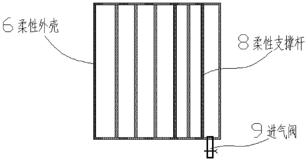
The invention relates to a combination mold and working method for automatic laying of composite materials. The combination mold includes a main mold tire, a flexible insert mold, a stopper and a rigid insert mold, and the main mold tire is used for forming a composite material blank , when the prepreg used to form the composite material blank is laid on the surface of the main mold tire, the flexible insert mold is a rigid airbag structure, which is set on the edge profile of the main mold tire, and the flexible insert mold There is an air inlet valve on the top, and the stopper is set on the side end surface of the main mold tire, and the stopper is at least higher than the bottom surface of the flexible insert mould, which is used to limit it. When the prepreg laying is completed, the rigid insert The block mold replaces the flexible insert mold and is set on the edge profile of the main mold tire, and the upper surface profile of the rigid insert mold matches the surface shape of the composite material blank, and the working surface of the upper surface of the flexible insert mold The curvature is less than the curvature of the working face of the upper surface of the rigid insert mold.

Description

technical field [0001] The invention relates to the technical field of composite material parts manufacturing, in particular to a composite mold and working method for automatic laying of composite materials. Background technique [0002] Resin-based composite materials are widely used in aerospace, high-speed rail and other military or civilian fields. The application structure is becoming more and more complex, and the requirements for manufacturing quality and manufacturing efficiency are also getting higher and higher. At present, the manufacture of resin-based composite parts is still mainly manual, but with the development of automation and intelligent technology, more and more automated manufacturing technologies are applied to the field of composite material molding manufacturing, and automatic wire laying based on prepreg The manufacturing of composite material parts is an automated manufacturing technology that has developed rapidly in recent years. This technology...

Claims


Application Information

Patent Timeline
Patent Type & Authority Patents(China)
IPC IPC(8): B29C70/30B29C70/54B29C33/00
CPCB29C70/30B29C70/54B29C33/00
Inventor 崔海超翟全胜苗春卉张洋刘立朋
Owner AVIC BEIJING AERONAUTICAL MFG TECH RES INST
Learn More