
Laminated shear wall closely-spliced vertical joint structure and construction method

A superimposed shear wall and vertical technology, which is applied in the direction of building structure, walls, structural elements, etc., can solve the problems that the prefabricated construction cannot be used on the construction site, the difficulty of binding steel bars in the vertical post-casting section, and the penetration of horizontal connecting steel bars Difficulties and other problems, to achieve the effect of on-site construction quality control, reduction of formwork and steel binding work, and high construction efficiency

Pending Publication Date: 2020-09-22
CHINA INST OF BUILDING STANDARD DESIGN & RES
View PDF0 Cites 2 Cited by
  • Summary
  • Abstract
  • Description
  • Claims
  • Application Information

AI Technical Summary

Problems solved by technology

In the vertical post-casting section, the horizontal connecting steel bars, vertical steel bars and stirrups are densely packed, and the horizontal connecting steel bars need to pass through the steel trusses of the prefabricated walls on both sides of the vertical joint, which makes it difficult to penetrate the horizontal connecting steel bars on site, and the work efficiency is low. It is difficult to bind the steel bars in the backward pouring section, and the support modulus is large, so the construction site cannot take advantage of the prefabricated construction

Method used


Image

  • Laminated shear wall closely-spliced vertical joint structure and construction method
  • Laminated shear wall closely-spliced vertical joint structure and construction method
  • Laminated shear wall closely-spliced vertical joint structure and construction method

Examples


Embodiment 1

[0069] Preferred Embodiment 1, Improved Type 1 The inner walls of the precast concrete panels 11 on both sides of the precast wall can adopt the natural pouring surface formed during the production of the laminated shear wall without special treatment. Further, you can also press Figure 17 In the area of ​​the inner wall of the precast concrete wall panel 11 close to the installation joint 3, a groove 111 is arranged along the height direction of the wall. After the post-cast concrete in the cavity 12 is poured, a shear bond is formed between the precast concrete and the post-cast concrete at the position of the groove 111. To strengthen the shear force transmission at the vertical joint position.

[0070] Specifically, the groove 111 is formed by pressing with a special mold after the pouring of the corresponding precast concrete wall plate 11 is completed and before the initial setting of the concrete, or it can also be formed by using a special tool to remove the concrete ...


PUM

PropertyMeasurementUnit
Diameteraaaaaaaaaa

Abstract

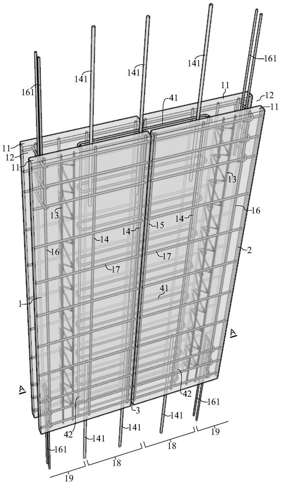
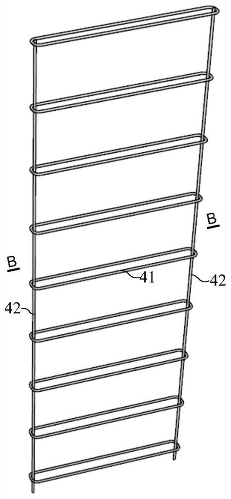
The invention discloses a laminated shear wall closely-spliced vertical joint structure and a construction method. Only a mounting joint with the width of about 20 mm is arranged between adjacent prefabricated walls, a specially designed vertical joint mold is adopted to improve the capacity of a cantilever section at the end part of a prefabricated concrete wallboard of the prefabricated wall forresisting the pressure of a concrete pouring side mold, the distance between a steel bar truss and the side edge of the prefabricated wall is increased, an internal large cavity is formed in the position of the closely-spliced vertical joint, and a horizontally-connected steel bar shaping steel bar cage is arranged in the cavity in a back arranged mode to achieve lap joint of horizontally-distributed steel bars of the prefabricated wall on the two sides of the vertical joint. According to the construction method, closely-spliced construction of the vertical joint of the laminated shear wall can be achieved, the vertical joint horizontal connecting steel bars are shaped steel bar cages produced industrially, the mold is a shaped universal mold, the standardized operation degree of steel bar penetrating and mold supporting in site construction of vertical joint is high, the site construction efficiency can be improved, the construction quality can be improved, meanwhile, the construction cost can be reduced through standardization and universalization.

Description

technical field [0001] The invention belongs to the technical field of buildings, and relates to a superimposed shear wall, in particular to a dense vertical joint structure and a construction method of a superimposed shear wall. Background technique [0002] Composite shear wall structure processing and installation accuracy requirements are low, the side of the prefabricated wall can be free of ribs, and the connection of adjacent prefabricated hollow wall panels can be realized by means of cavities, so that the side molds in the prefabricated wall production stage can be realized without opening holes, and the molds can be standardized and generalized It is a type of prefabricated concrete shear wall structure system suitable for residential buildings in my country. Representative systems include double-sided laminated shear wall structures. [0003] When the prefabricated wall is connected at the non-edge component position in the double-sided laminated shear wall structu...

Claims


Application Information

Patent Timeline
IPC IPC(8): E04B2/56E04B2/00E04C5/16E04G21/12E04G11/08E04G17/065
CPCE04B2/00E04B2/56E04C5/165E04G11/08E04G17/0655E04G21/12
Inventor 肖明韩文龙郁银泉
Owner CHINA INST OF BUILDING STANDARD DESIGN & RES
Learn More