Ultrafast laser pulse width measuring device and control method thereof

A pulse width, ultrafast laser technology, applied in the field of laser applications, can solve problems such as large insertion loss, cumbersome operation, and reduced laser spot quality, and achieve the effects of low structural cost, easy operation, and improved work efficiency

Inactive Publication Date: 2020-09-22
广州市固润光电科技有限公司
View PDF5 Cites 1 Cited by
  • Summary
  • Abstract
  • Description
  • Claims
  • Application Information

AI Technical Summary

Problems solved by technology

However, solution (1) not only requires high optical path adjustment, but also requires precise adjustment of the grating pair spacing, and requires a standard autocorrelator to calibrate the pulse width during use, which is cumbersome to operate; in addition, the use of gratings will cause greater insertion loss and lead to laser The quality of the spot...

Method used


Image

  • Ultrafast laser pulse width measuring device and control method thereof
  • Ultrafast laser pulse width measuring device and control method thereof
  • Ultrafast laser pulse width measuring device and control method thereof

Examples


Embodiment 1

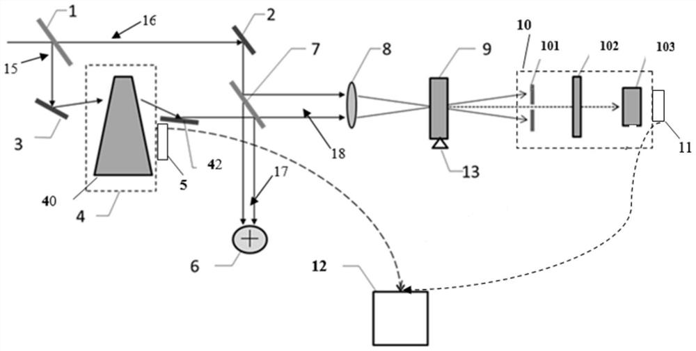
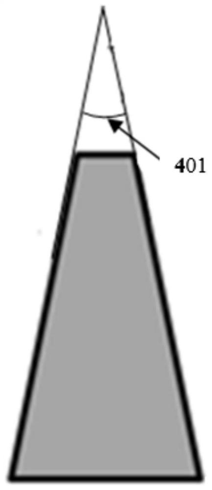
[0053] refer to Figure 2 to Figure 3 , the present embodiment improves a schematic diagram of an optical path of an ultrafast laser pulse width measuring device, including a beam splitting component, a first adjustable component 4, a lens 8, a rotating component, a second adjustable component 10, an optical path calibration component 6, and a processor 12 , wherein the beam splitting component includes a beam splitting mirror 1, a mirror 2, a mirror 3 and a beam splitting mirror 7, and the first adjustable component 4 includes a wedge prism 40 (facet angle 401 is less than 30°), a mirror 402, a first The adjustable base and regulator 5, the wedge prism 40 and the reflector 402 form a delayer placed on the first adjustable base, and the first adjustable base is connected to the controller 5, the beam splitter 1 and the reflector 3 are placed On the light incident side of the first adjustable component 4, the beam splitter 7 and reflector 2 are placed on the light output side o...

Embodiment 2

[0060] Such as Figure 4As shown, a schematic diagram of the optical path of an ultrafast laser pulse width measurement device improved in this embodiment, including a beam splitting component, a first adjustable component 4, an optical path calibration component 6, a lens 8, a rotating component, and a second adjustable component 10 And processor 12; The beam splitting part comprises beam splitter 1, reflector 2, reflector 3 and beam splitter 7, and the first adjustable component 4 comprises reflector 41, reflector 42, reflector 43, reflector 44, The regulator 5 and the first adjustable base, wherein the reflector 41, the reflector 42, the reflector 43 and the reflector 44 form a quadrilateral to form a time delayer, and the reflector 42 and the reflector 43 are placed on the first adjustable base , the adjuster 5 is connected with the first adjustable base; the rotating part comprises a barium metaphosphate crystal 9 (BBO crystal) and a rotating bracket 13 and the barium met...


PUM


Abstract

The invention discloses an ultrafast laser pulse width measuring device and a control method thereof. The device comprises a beam splitting part, a first adjustable part, a rotating part and a secondadjustable part, the first adjustable part comprises a time delay assembly and an adjuster, the time delay assembly is connected with the adjuster, the second adjustable part comprises a measuring assembly and a controller, and the measuring assembly is connected with the controller; a to-be-measured light beam is divided into a first light beam and a second light beam by a beam splitting part; the reliability of pulse width measurement is ensured; based on the first adjustable part, the accurate adjustment of the optical path of the first light beam can be quickly realized. Based on the rotating part and the second adjustable part, beam pulse detection of any angle polarization state and measurement of autocorrelation signals of the beam pulse detection are achieved, so that the pulse width of a to-be-detected beam is output accurately with high precision, the device is low in structure cost and easy and convenient to operate, operation of professionals is not needed, and the detectable work efficiency is improved.

Description

technical field [0001] The invention relates to the technical field of laser applications, in particular to an ultrafast laser pulse width measuring device and a control method thereof. Background technique [0002] Since the laser was invented in the 20th century, it has been hailed as "the fastest knife", "brightest light" and "the most accurate ruler" for its outstanding characteristics; Another great invention. The generation of laser light requires at least the following three elements: a working substance that realizes particle population inversion, an excitation source that excites atoms, and an optical resonant cavity that realizes light amplification. With the continuous development of laser technology, laser is widely used in communication, industry, military and medical fields due to its good monochromaticity, strong coherence, good directionality and high energy concentration. Among them, the quality of laser spot is the main reason affecting the application of...

Claims


Application Information

Patent Timeline
IPC IPC(8): G01J11/00G01J1/42G01J1/04
CPCG01J1/0403G01J1/0411G01J1/0437G01J1/4257G01J11/00G01J2001/4238
Inventor 徐绪卿
Owner 广州市固润光电科技有限公司
Why Eureka
Try Eureka