Modeling method of laser arc composite heat source based on energy distribution coefficient

A composite heat source, laser arc technology, applied in CAD numerical modeling, special data processing applications, design optimization/simulation, etc., can solve the problem that the shape of the simulated molten pool is not well matched with the actual molten pool, and the heat source verification period is long, etc. problems, to achieve the effect of shortening the verification cycle and shortening the time-consuming

Active Publication Date: 2020-09-22
HOHAI UNIV CHANGZHOU
View PDF2 Cites 3 Cited by
  • Summary
  • Abstract
  • Description
  • Claims
  • Application Information

AI Technical Summary

Problems solved by technology

[0003] Aiming at the deficiencies of the prior art, the object of the present invention is to provide a modeling method of the laser arc composite heat source based on the energy distribution coefficient, to solve the problem of long heat source verification period and the difference between the simulated molten pool and the actual welding simulation in the prior art. The technical problem of poor fit of molten pool shape

Method used


Image

  • Modeling method of laser arc composite heat source based on energy distribution coefficient
  • Modeling method of laser arc composite heat source based on energy distribution coefficient
  • Modeling method of laser arc composite heat source based on energy distribution coefficient

Examples


Embodiment example 1

[0073] The 150mm×80mm×18.4mm alloy steel plate is cut and processed, a 30° V-shaped groove is made, and three-pass composite heat source multi-pass welding is performed. After cutting and surface treatment of X100 high-strength pipeline steel, there will be chips and oil stains on its surface. Therefore, before welding, sand the sample with sandpaper, then clean the sample with acetone, and finally wipe it with alcohol. The process parameters shown in Table 1 are used for welding.

[0074] Table 1: Welding process parameters used in Example 1

[0075]

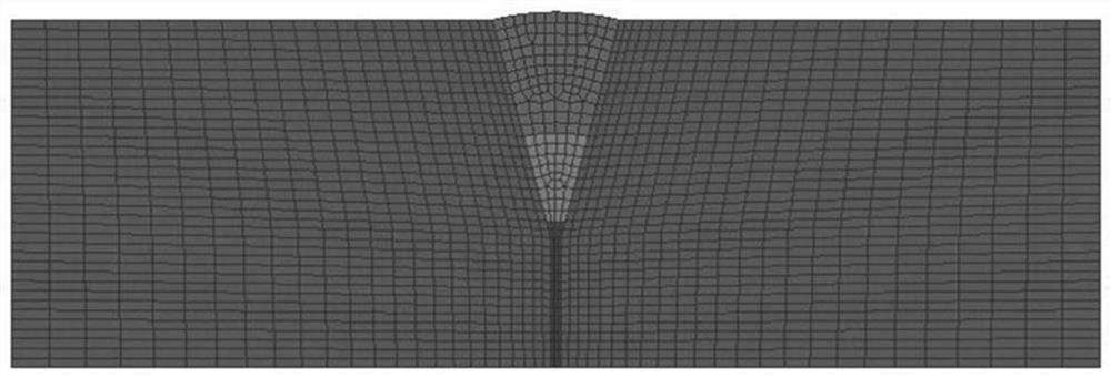
[0076] Through the hybrid welding experiment, the macroscopic appearance of the laser arc hybrid welding seam is obtained. Specific as image 3 As shown, it is a schematic diagram of the grid model of the hybrid welding joint in the method embodiment of the present invention. Then, according to the shape of the weld, the dimensions of the heat source model of laser arc hybrid welding are obtained, and then according to t...

Embodiment example 2

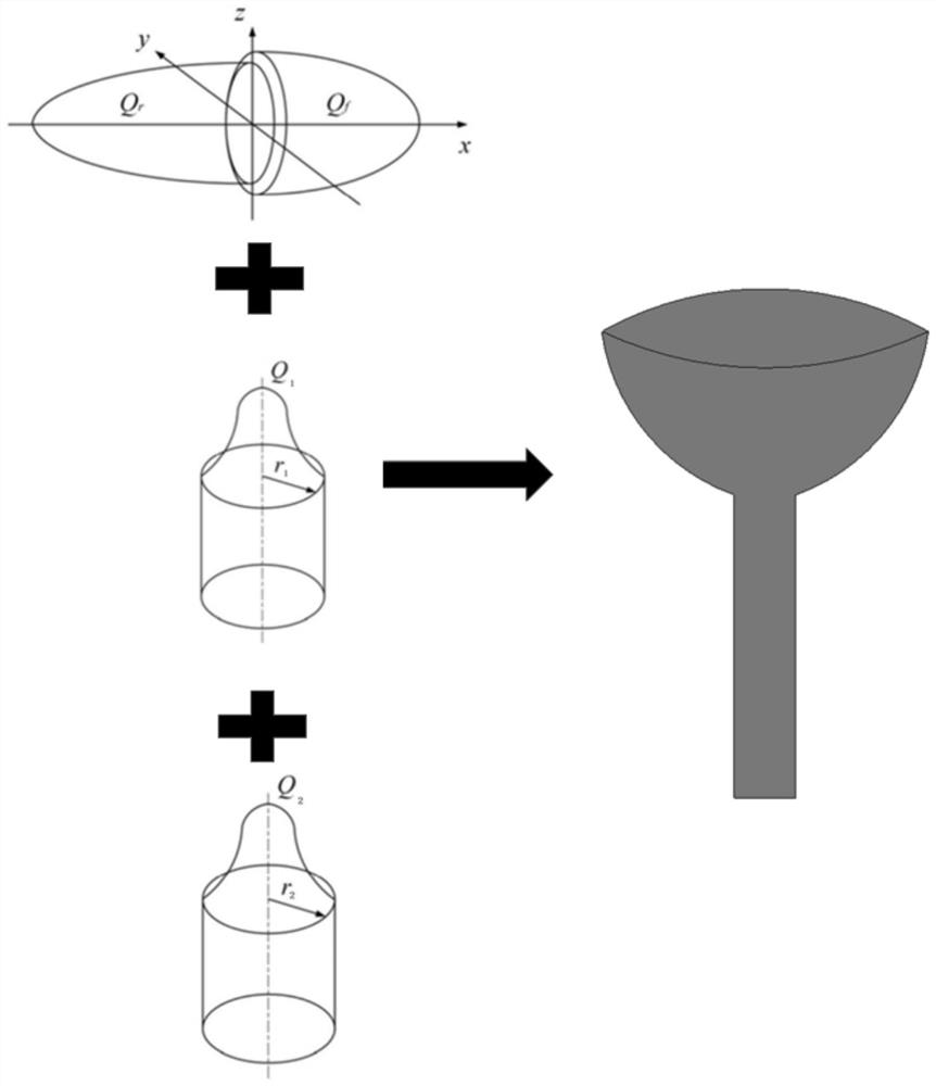
[0079] Cut the 150mm × 80mm × 18.4mm alloy steel plate, open a 30° V-shaped groove, and perform three-pass composite heat source multi-pass welding, specifically as figure 2 Shown is a schematic diagram of the composition of the laser arc composite heat source model in the method embodiment of the present invention. After cutting and surface treatment of X100 high-strength pipeline steel, there will be chips and oil stains on its surface. Therefore, before welding, sand the sample with sandpaper, then clean the sample with acetone, and finally wipe it with alcohol. The process parameters shown in Table 2 are used for welding.

[0080] Table 2: Welding process parameters used in Example 2

[0081]

[0082] Through the hybrid welding experiment, the macroscopic appearance of the laser arc hybrid welding seam is obtained. Then, according to the shape of the weld, the dimensions of the heat source model of laser arc hybrid welding are obtained, and then according to the com...


PUM


Abstract

The invention discloses a modeling method of a laser arc composite heat source based on an energy distribution coefficient in the technical field of laser welding, and aims at solving the technical problems that in the prior art, the heat source checking period is long during welding simulation, and the shape goodness of fit of a simulated molten pool and an actual molten pool is not high. The method comprises the steps of acquiring the parameters of an actual molten pool; constructing a laser arc composite heat source model based on a pre-constructed energy distribution coefficient model between any two component heat sources, acquiring the parameters of a simulated molten pool based on the laser arc composite heat source model; and comparing the parameters of the simulated molten pool with the parameters of the actual molten pool to obtain the goodness of fit of the simulated molten pool relative to the actual molten pool, judging whether the goodness of fit reaches a preset threshold value or not, adjusting the heat source parameters, and taking the laser arc composite heat source model when the goodness of fit reaches the preset threshold value as a final model of the laser arccomposite heat source.

Description

technical field [0001] The invention relates to a modeling method of a laser arc composite heat source based on an energy distribution coefficient, and belongs to the technical field of laser welding. Background technique [0002] With the rapid development of computational simulation technology, welding simulation technology has gradually attracted people's attention. More and more engineers use simulation technology to study the welding process and phenomena, and then optimize the welding process in order to effectively control welding deformation and welding defects. At present, the simulation technology for welding is not mature enough, and there are technical problems such as a long heat source calibration cycle, and the shape of the simulated molten pool does not match the actual molten pool shape. Contents of the invention [0003] Aiming at the deficiencies of the prior art, the object of the present invention is to provide a modeling method of the laser arc compos...

Claims


Application Information

Patent Timeline
Patent Type & Authority Applications(China)
IPC IPC(8): G06F30/20G06F111/10
CPCG06F30/20G06F2111/10
Inventor 严春妍张浩朱子江易思黄晏程侯佳兵
Owner HOHAI UNIV CHANGZHOU
Why Eureka
Try Eureka