
All-metal multi-beam lens antenna based on quasi-conformal transformation optics

A lens antenna, conformal transformation technology, applied to antennas, electrical components, etc., can solve the problems of low efficiency of the central operating frequency aperture of the antenna, the practicability is questionable, and the antenna profile is reduced, so as to achieve easy integration and improve the antenna radiation pattern. , high precision effect

Active Publication Date: 2020-09-22
UNIV OF ELECTRONICS SCI & TECH OF CHINA
View PDF10 Cites 4 Cited by
  • Summary
  • Abstract
  • Description
  • Claims
  • Application Information

AI Technical Summary

Problems solved by technology

In 2014, Carolina Mateo-Segura et al. published an article entitled "Flat Luneburg Lens via TransformationOptics for Directive Antenna Applications" in IEEE Transactions on Antennas and Propagation, using transformation optics to compress the spherical Luneburg lens into a flat Luneburg lens, It not only retains the inherent excellent focusing characteristics of the Lunberg lens, but also effectively reduces the profile of the antenna. By switching the beam to scan to ±34°, but the central operating frequency of the antenna is 10GHz and the lens is a pure dielectric material, which can be extended to the millimeter wave frequency band The practicality of the
In 2019, in an article entitled "ARadial Transformation-Optics Mapping for FlatUltra-Wide-Angle Dual-Polarized Stacked GRIN MTM Luneburg Lens Antenna" published in IEEE Transactions on Antennas and Propagation, Y.Su et al. used a multilayer PCB board Process and metamaterial technology, realized a dual-polarized planar Lunberg lens antenna, but the central operating frequency of the antenna is still 10GHz and the aperture efficiency is low

Method used


Image

  • All-metal multi-beam lens antenna based on quasi-conformal transformation optics
  • All-metal multi-beam lens antenna based on quasi-conformal transformation optics
  • All-metal multi-beam lens antenna based on quasi-conformal transformation optics

Examples


Embodiment Construction

[0019] specific implementation plan

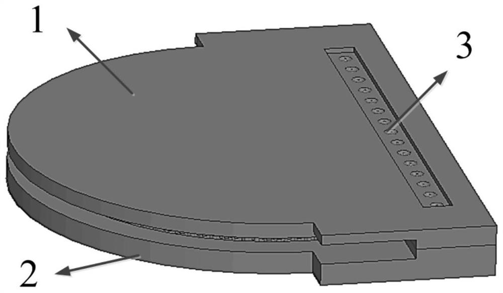
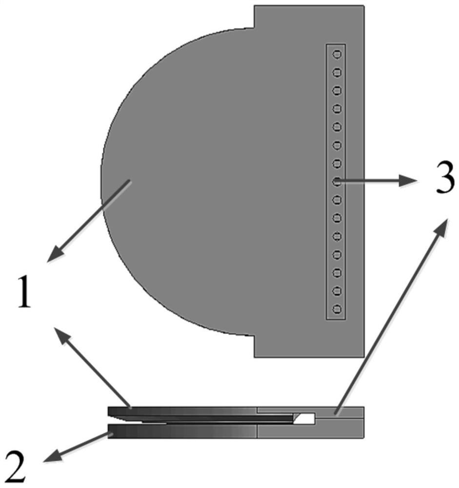
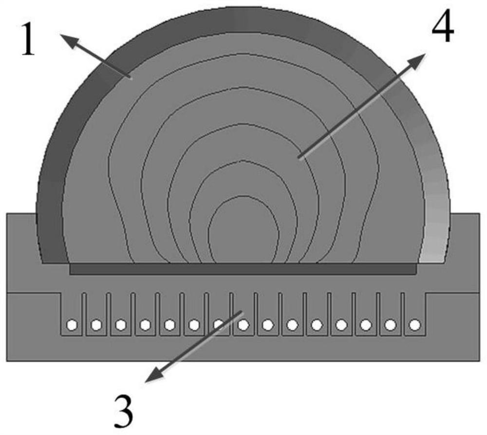
[0020] figure 1 and figure 2 The three-dimensional design structure of an all-metal multi-beam lens antenna based on quasi-conformal transformation optics is exemplarily described. As shown in the figure, the structure includes a metal parallel plate upper layer (1), a metal parallel plate lower layer (2) and a 1×15 open wave wave line array feed source (3).

[0021] The upper layer of the metal parallel plate (1) and the lower layer of the metal parallel plate (2) are two metal plates with completely different inner structures. The 1×15 open wave line array feed (3) is also divided into upper and lower parts along the horizontal plane for the convenience of processing. The two parts are respectively placed on the upper layer (1) of the metal parallel plate and the lower layer (2) of the metal parallel plate, and the overall structure can be easily assembled and fixed together by metal screws. The open-ended waveguide feed has the char...


PUM


Abstract

The invention discloses an all-metal multi-beam lens antenna based on quasi-conformal transformation optics. The all-metal multi-beam lens antenna is applied to multi-beam directional communication and beam scanning. A basic structure of the antenna comprises a linear feed source array composed of a plurality of open ridge waveguide antennas, and upper and lower metal plates which are parallel toeach other. The lens antenna is filled with air, a metal cylinder is loaded on the inner side of a metal plate or different equal-height surfaces are etched, equivalent dielectric constant distribution required after the shape of the lens is changed is realized, a series of design and engineering application problems encountered in the process of designing the dielectric luneberg lens antenna working in the 5G millimeter wave frequency band are solved, and the lens antenna can be better applied to use scenes of multi-beam directional communication and beam scanning and corresponding market requirements. Based on the basic structure of the antenna, other specific embodiments of the invention can be formed by reasonably changing the antenna shape, the antenna size and the feed source form.

Description

[0001] The invention belongs to the technical field of antennas, and relates to an all-metal lens antenna, specifically an all-metal multi-beam lens antenna based on quasi-conformal transformation optics for multi-beam directional communication and beam fast electrical scanning, especially suitable for working in 5G mm The usage scenarios of wave frequency band and wide angle beam scanning. Background technique [0002] In recent years, with the rapid development of 5G communication systems, multi-beam antennas for millimeter wave bands have attracted much attention. The multi-beam antenna has the characteristics of high gain and wide-angle beam scanning, which can effectively solve the shortcomings of small spatial coverage and large spatial loss of electromagnetic waves in the millimeter wave frequency band. Based on the above requirements, the present invention designs an all-metal multi-beam lens antenna based on quasi-conformal transformation optics. [0003] The traditi...

Claims


Application Information

Patent Timeline
IPC IPC(8): H01Q19/06H01Q15/02
CPCH01Q15/02H01Q19/062
Inventor 杨仕文刘坤宁屈世伟陈益凯黄明胡俊
Owner UNIV OF ELECTRONICS SCI & TECH OF CHINA
Learn More