
An Inverted Step Shaft Structure and Blowout Reduction Method

A step-type, vertical well technology, applied to underwater structures, infrastructure engineering, drainage structures, etc., can solve the problems that cannot avoid the possibility of blowout, increase the pressure change of pipelines, and troublesome maintenance of vertical wells, so as to reduce the occurrence of vertical well blowout, The effect of stable air pressure and increased length

Active Publication Date: 2021-09-21
NANJING HYDRAULIC RES INST
View PDF2 Cites 0 Cited by
  • Summary
  • Abstract
  • Description
  • Claims
  • Application Information

AI Technical Summary

Problems solved by technology

To sum up, the reduction measures that have been proposed so far mainly include the following: (1) Increase the diameter of the vertical shaft. It is believed that increasing the diameter of the vertical shaft (to the same size as the main pipeline) can reduce the instantaneous extreme pressure when the blowout occurs, However, this method cannot avoid the possibility of blowout, and the diameter of the shaft cannot be increased indefinitely in practical applications; (2) A manhole cover with small holes is installed on the top of the shaft. The principle of this method is to reduce the extreme value of water flow pressure. Constrain the flux of the shaft to suppress the spraying of the water-steam mixture. However, this method often hinders the outflow of gas when the blowout intensity is high, and increases the pressure change in the pipeline, which cannot avoid the possibility of blowout; (3) Install it under the well cover Buffer structures, such as elastically supported rubber balls or baffles, etc., are designed to dissipate energy and separate water and air from jet streams, but they also bring troubles to shaft maintenance.

Method used


Image

  • An Inverted Step Shaft Structure and Blowout Reduction Method
  • An Inverted Step Shaft Structure and Blowout Reduction Method
  • An Inverted Step Shaft Structure and Blowout Reduction Method

Examples


Embodiment 1

[0037] The schematic diagram of the multi-stage connecting urban drainage pipe shaft structure is shown in figure 1 , the vertical shaft 3 is arranged on the top of the underground pipeline 1 to communicate with the underground pipeline 1 and the ground 2 , and the well cover 5 is arranged on the top of the vertical shaft 3 .

[0038] The shape of one side of the shaft 3 is stepped (shaft step 8), mirrored along the axis of the hole, the width of the step is larger than that of the underground pipeline 1, and the material is steel frame, reinforced concrete, high-strength synthetic material, etc., which can be integrally formed or assembled .

[0039]The first step of the shaft step 8 is flush with the ground 2, and a cylinder is dug out in the center, which is 3 shafts; the last step is connected to the top of the underground pipeline 1, and the slope of the middle step is i, generally i=30° ~60° is appropriate; the backfill 4 above the steps is flush with the ground 2. Des...

Embodiment 2

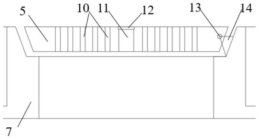
[0043] The shaft 3 communicates with the atmosphere on the ground 2 and the underground pipeline 1 , and the manhole cover 5 assembly is arranged on the top of the shaft 3 . The structure of manhole cover 5 components is as follows Figure 5 to Figure 6 As shown, it mainly includes the following components: well cover cavity 504, well cover 5 base, well cover support 505, well cover hinge 506, well cover rib 501, rib track 502, vent hole 10, middle hole, well cover 5 handles, limit Bit soft rope 503, hook, cushion 508. The well cover 5 is a conical body with a circular (or square) flat plate. When in use, the flat plate is placed horizontally and flush with the ground 2. The manufacturing material is generally cast iron, plastic, concrete or synthetic material, and the gravity is G.

[0044] The shape of the well cover cavity 504 is an inverted cone, and the cross-sectional shape is an inverted isosceles triangle. The base angle of the isosceles triangle is less than 60°, whi...


PUM


Abstract

The invention relates to an inverted stepped shaft structure and a blowout reduction method thereof. The shaft is arranged on the top of an underground pipeline to communicate with the underground pipeline and the ground, and the well cover is arranged on the top of the shaft. The shape of one side of the shaft is stepped and mirrored along the axis of the hole. The width of the step is larger than that of the underground pipeline, and it can be integrally formed or assembled. The first step of the shaft step is flush with the ground, and a cylinder is dug out in the center, which is the shaft mouth; the last step is connected to the top of the underground pipeline, and the slope of the middle step is 30° to 60°; the backfill above the step and The ground is level. The present invention tans the driving pressure difference for blowout formation, the manhole cover is provided with ventilation holes to connect the underground pipeline and the ground atmosphere, balances the non-constant air pressure in the vertical shaft and underground pipeline, balances the air pressure in the pipeline in advance, and tansizes the driving pressure difference for the blowout phenomenon. value, effectively suppressing the formation of blowout conditions.

Description

technical field [0001] The invention belongs to the technical field of municipal engineering and water conservancy engineering, and in particular relates to an inverted stepped shaft structure and a blowout relief method thereof. Background technique [0002] In municipal engineering, the underground pipe network is criss-crossed, including sewage pipe network, cable pipe network, water supply pipe network, etc. Manhole covers are often provided on the street floor to block the entrance of the pipe network. The structure connecting the ground and underground pipe networks is often called It is a shaft, which usually has the functions of collecting water, ventilating, and passing people. Generally, these shafts are designed as a well-shaped pipe with a vertical wall, and the upper part is sealed with a manhole cover. [0003] In recent years, with the solidification of the underlying surface of the city, the drainage load of the urban drainage pipe network has increased. Ge...

Claims


Application Information

Patent Timeline
Patent Type & Authority Patents(China)
IPC IPC(8): E02D29/12E02D29/14E03F5/02E03F5/08
CPCE02D29/12E02D29/125E02D29/14E02D29/1436E02D29/1463E03F5/02E03F5/08
Inventor 王芳芳吴时强吴修锋戴江玉高昂杨倩倩张宇黄标王小东崔鹏飞徐鹏俞雷赵宇航徐准沙海明杜庭宝何建明樊顾飞
Owner NANJING HYDRAULIC RES INST
Learn More