Cast-in-place concrete built-in thermal insulation wall structure

A technology for thermal insulation walls and concrete, which is applied in thermal insulation, walls, building components, etc., can solve the problems of low thermal insulation performance of concrete walls, and achieve the effects of reducing air bubbles, improving strength, and simple overall structure of the wall.

Pending Publication Date: 2020-09-25
山东赛昌新型材料有限公司
View PDF0 Cites 2 Cited by
  • Summary
  • Abstract
  • Description
  • Claims
  • Application Information

AI Technical Summary

Problems solved by technology

[0004] The invention provides a cast-in-situ concrete built-in thermal insulation wall structure and construction method, which solves the problem of the thermal insulation of the concrete w...

Method used


Image

  • Cast-in-place concrete built-in thermal insulation wall structure
  • Cast-in-place concrete built-in thermal insulation wall structure
  • Cast-in-place concrete built-in thermal insulation wall structure

Examples


Embodiment 1

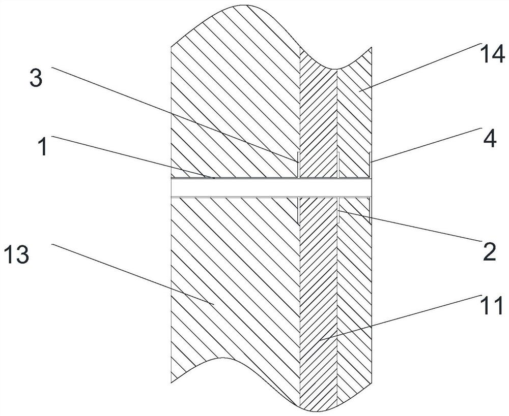
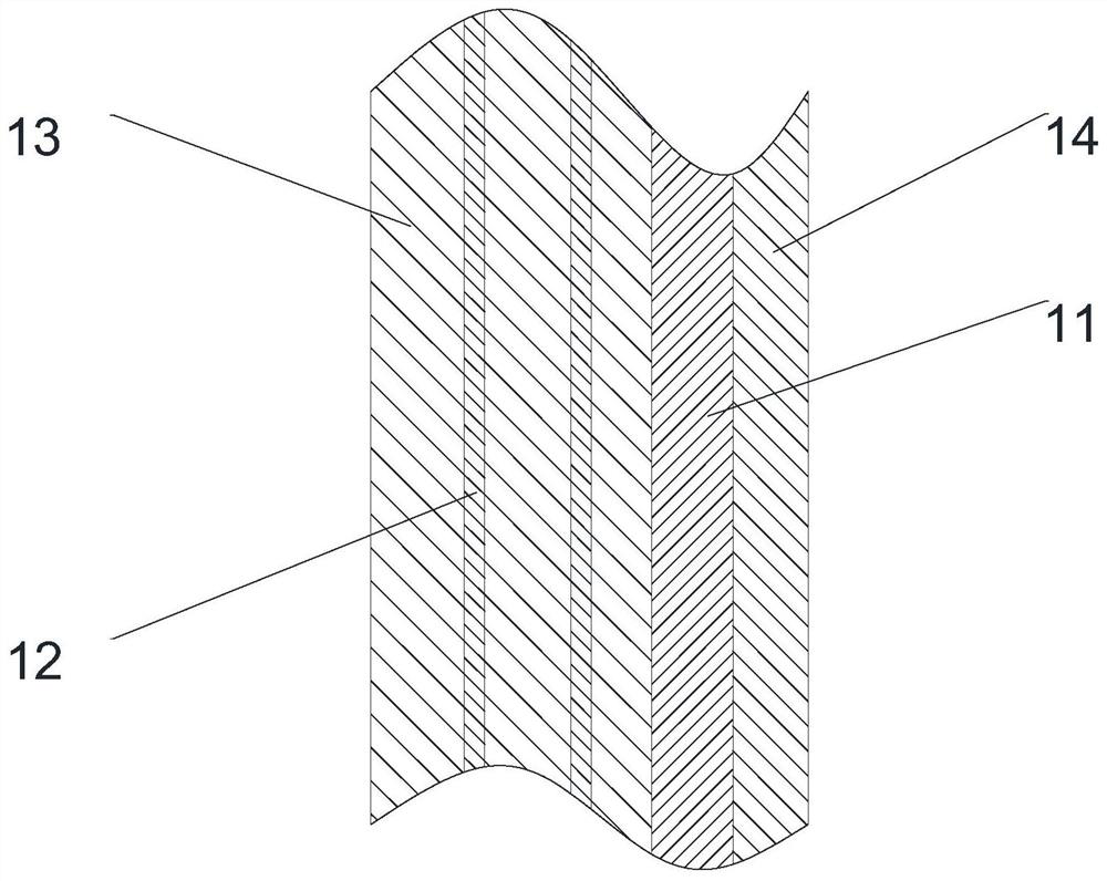
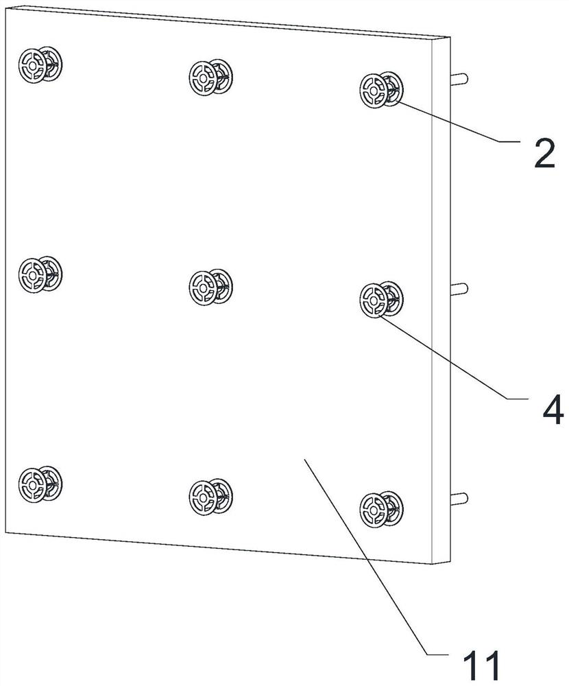
[0047] Such as Figure 1-8 As shown, the cast-in-place concrete built-in thermal insulation wall structure includes an inner wall layer 13, an outer wall layer 14, an insulating layer 11 between the inner wall layer 13 and the outer wall layer 14, and the inner wall layer 13, the insulating layer 11 and the The pipe body 1 of the outer wall layer 14, the axial passage of the pipe body 1 runs through the pipe body 1 to form openings at both ends of the pipe body 1, and the outer wall of the pipe body 1 is provided with a first limiting piece 2 and a second limiting piece 3 , The insulation layer 11 is located between the first limiting piece 2 and the second limiting piece 3 . During pouring, the pipe body 1 passes through the insulation layer 11 to support the inner and outer formwork, and the tension bolts pass through the pipe body 1 to fasten the inner and outer formwork. Position the inner and outer formwork. The cast-in-place concrete built-in thermal insulation wall st...

Embodiment 2

[0060] The difference between this embodiment and Embodiment 1 is that the end piece 4 is fixedly connected with the tube body 1, the first limiting piece 2 is integrally formed with the tube body 1, the outer wall of the tube body 1 is provided with a buckle structure, and the second limiting piece The piece 3 is detachably connected with the tube body 1 through a buckle structure. The embedded structure 5 is a bump. The length of the region along the axial direction of the tube body 1 where the embedded structure 5 is provided on the outer wall of the tube body 1 is 8 cm.

[0061] A mortar layer is arranged on the side of the insulation layer close to the first limiting piece. Mesh cloth is arranged in the mortar layer. The mortar layer and grid cloth can improve the strength of the insulation layer and prevent the insulation layer from being damaged during pouring and vibration.

Embodiment 3

[0063] The difference between this embodiment and Embodiment 1 is that the outer wall of the tube body 1 is provided with a barb structure, and the second limiting piece 3 is connected with the tube body 1 through the barb structure. The embedded structure 5 is a barb.

[0064] A mortar layer is arranged on the side of the insulation layer close to the first limiting piece. A mortar layer is arranged on the side of the insulation layer close to the second limiting piece.


PUM


Abstract

The invention relates to the field of building construction, and solves the problem of low thermal insulation performance of a concrete wall body caused by the fact that through holes for a connectingpiece and a split bolt to penetrate through are formed in a thermal insulation layer of the concrete wall body in the prior art. A cast-in-place concrete built-in thermal insulation wall structure comprises an inner wall layer, an outer wall layer, a thermal insulation layer located between the inner wall layer and the outer wall layer and a pipe body penetrating through the inner wall layer, thethermal insulation layer and the outer wall layer, an axial channel of the pipe body penetrates through the pipe body to form openings in the two ends of the pipe body, a first limiting piece and a second limiting piece are arranged on the outer side wall, and the thermal insulation layer is located between the first limiting piece and the second limiting piece. The split bolt penetrates throughthe pipe body to fasten an inner template and an outer template, and the tension of the split bolt and the supporting force of the connecting piece act synergistically to position the inner template and the outer template. Through holes cannot be formed in the cast-in-place concrete built-in thermal insulation wall structure due to the fact that split bolts are arranged, the number of the throughholes in the cast-in-place concrete built-in thermal insulation wall is reduced, heat loss is reduced, and the thermal insulation performance of the wall is improved.

Description

technical field [0001] The invention relates to the field of building construction, in particular to a cast-in-situ concrete built-in thermal insulation wall structure and a construction method. Background technique [0002] The structure of the cast-in-place concrete built-in thermal insulation wall is inner wall layer-insulation layer-external wall layer, and multiple connectors are arranged on the insulation layer. The rod body of the connector of the existing cast-in-situ concrete built-in thermal insulation wall is a solid rod. In addition, the inner and outer wall layers of the cast-in-situ concrete built-in thermal insulation wall need to be fastened with tension bolts before the inner and outer formworks are poured, so that the tension of the tension bolts and the supporting force of the connectors work together to integrate the inner and outer forms. Outer template positioning. In order to allow the pull bolts to pass through, special through holes need to be prov...

Claims


Application Information

Patent Timeline
IPC IPC(8): E04B2/00E04B2/84E04B1/76
CPCE04B1/76E04B2/00E04B2/84Y02B30/90Y02A30/00
Inventor 刘文起
Owner 山东赛昌新型材料有限公司
Why Eureka
Try Eureka