Variable diameter chamfering-based top plate high-directional drilling gas extraction device

A technology for directional drilling and gas drainage, which is applied in gas discharge, earth-moving drilling, safety devices, etc., can solve the problems of inability to cope with the geological environment, low efficiency, low drilling efficiency, etc., so as to improve drilling efficiency and improve drilling efficiency. Hole expansion efficiency and leakage avoidance effect

Active Publication Date: 2020-09-25
GUIZHOU UNIV OF ENG SCI
View PDF4 Cites 2 Cited by
  • Summary
  • Abstract
  • Description
  • Claims
  • Application Information

AI Technical Summary

Problems solved by technology

[0002] At present, gas outbursts in coal mines are common, especially in goafs where few people pay attention to gas outbursts. The fundamental measure to solve such problems is to reduce the gas content in coal seams, so as to ensure the safety of workers. Ordinary drilling rig construction When high-position directional drilling of the top plate is performed, the drilling efficiency is low. One of the reasons is that the structure of the drill bit is relatively simple, and the rotary cutting of the cutter head alone cannot cope with the complex geological environment. In addition, during the drilling process, a small amount of The gas is gradually released. If this is ignored and not collected, accidents may occur. In addition, in the subsequent drainage process after drilling, the fracture structure around the drilling will change as the gas concentration decreases. In order to improve the stability of the subsequent hole sealing, it is necessary to ream the hole in the hole for subsequent grouting and sealing. However, the existing drilling equipment has simple functions, and it can only realize drilling but not reaming. Therefore, the existing The operation process is often to pull out the drill pipe after drilling and replace it with a reaming bit for reaming, resulting in low overall efficiency

Method used


Image

  • Variable diameter chamfering-based top plate high-directional drilling gas extraction device
  • Variable diameter chamfering-based top plate high-directional drilling gas extraction device
  • Variable diameter chamfering-based top plate high-directional drilling gas extraction device

Examples


Embodiment Construction

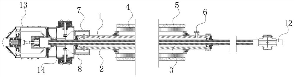
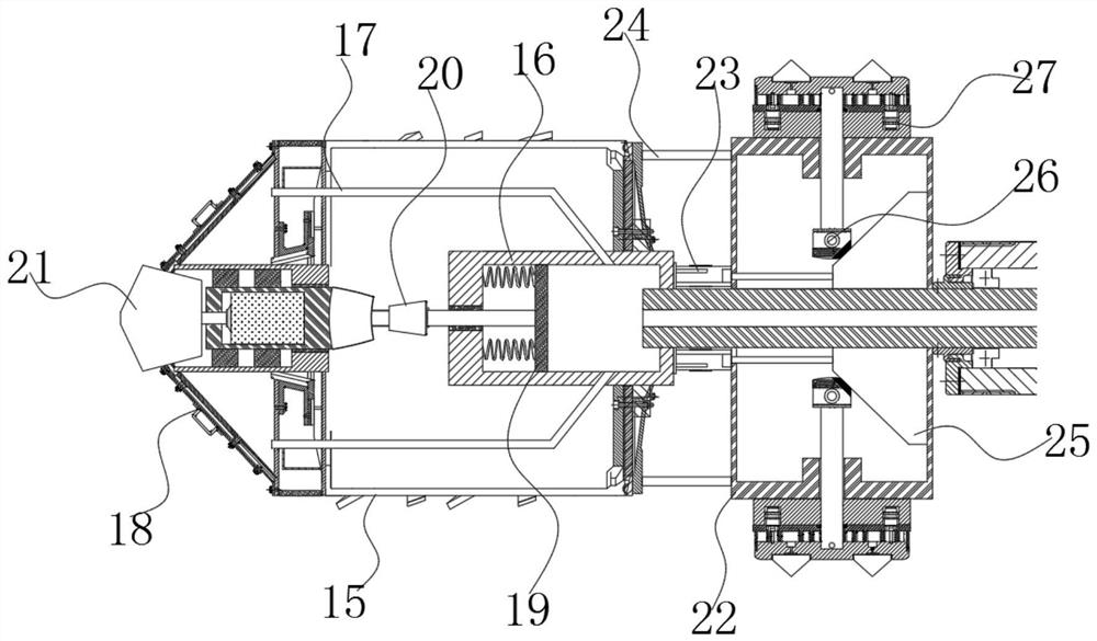
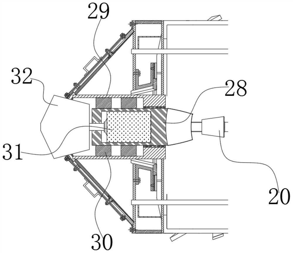
[0038] see Figure 1~5 , in an embodiment of the present invention, a roof high-position directional drilling gas drainage device based on variable-diameter reaming, which includes a drill pipe 1, a drainage cylinder 2, a drill assembly, a variable-diameter reaming assembly, and a support assembly, wherein the The central hole at one end of the drill pipe 1 far away from the drill hole is connected to the water supply pipeline 12 by a rotary joint, and the water supply pipeline 12 can provide flushing fluid for the central hole of the drill pipe 1,

[0039] The outer circumference of the drill pipe 1 located in the borehole is covered with a drainage cylinder 2. During drilling and reaming, the gas in the borehole can enter the drainage cylinder 2 and pass through the gas collection pipe. 6 Collected in an external storage tank to achieve pre-extraction and avoid gas leakage;

[0040] The drill rod 1 is installed in the extraction cylinder 2 in a sealed and rotating manner, a...


PUM


Abstract

The invention discloses a variable diameter chamfering-based top plate high-directional drilling gas extraction device, which comprises a drill rod, an extraction drum, a drill bit component, a variable diameter chamfering component and a supporting component, wherein a center hole in one end, away from a drill hole, of the drill rod is connected with a water supply pipeline by a rotating joint; the water supply pipeline can supply flushing fluid to the center hole of the drill rod; the extraction drum is arranged on the outer circumference of the drill rod in the drill hole in a sleeving manner; during drilling and variable diameter chamfering, gas in the drill hole can enter the extraction drum, and is collected into an external storage tank through a gas collection pipe, thus realizingpreliminary extraction and preventing gas leakage; the drill rod is hermetically and rotatably arranged in the extraction drum; furthermore, one end, away from the drill hole, of the drill rod is driven by an underground drill rig, and the other end of the drill rod is provided with the variable diameter chamfering component and the drill bit component in sequence; meanwhile, during drilling and variable diameter chamfering, the drill rod extends into the drill hole, and then is supported by the supporting component into the inner wall of the drill hole.

Description

technical field [0001] The invention belongs to the technical field of gas drainage, in particular to a gas drainage device for high-position directional drilling on a top plate based on variable-diameter reaming. Background technique [0002] At present, gas outbursts in coal mines are common, especially in goafs where few people pay attention to gas outbursts. The fundamental measure to solve such problems is to reduce the gas content in coal seams, so as to ensure the safety of workers. Ordinary drilling rig construction When high-position directional drilling of the top plate is performed, the drilling efficiency is low. One of the reasons is that the structure of the drill bit is relatively simple, and the rotary cutting of the cutter head alone cannot cope with the complex geological environment. In addition, during the drilling process, a small amount of The gas is gradually released. If this is ignored and not collected, accidents may occur. In addition, in the subse...

Claims


Application Information

Patent Timeline
IPC IPC(8): E21B7/00E21B7/28E21B10/32E21B10/00E21B10/60E21B10/36E21B17/10E21F7/00E21B21/00E21B43/00
CPCE21B7/00E21B7/28E21B10/00E21B10/32E21B10/36E21B10/602E21B17/1014E21B21/00E21B43/006E21F7/00
Inventor 许国胜范晓杰李回贵关金锋
Owner GUIZHOU UNIV OF ENG SCI
Why Eureka
Try Eureka