Continuous transformation large-transformation-range hydraulic transformer for high speed valve-controlled hydraulic cylinder

A technology of hydraulic transformers and high-speed valves, which is applied in the direction of fluid pressure converters, accumulator devices, fluid pressure actuators, etc., can solve problems such as large noise and vibration, application restrictions, and small pressure transformation range, and achieve unlimited Vibration and noise, easy control, less throttling effect

Active Publication Date: 2020-09-25
XUZHOU NORMAL UNIVERSITY
View PDF7 Cites 1 Cited by
  • Summary
  • Abstract
  • Description
  • Claims
  • Application Information

AI Technical Summary

Problems solved by technology

The disadvantage of the supercharged hydraulic cylinder's own structure is that its piston area ratio is fixed, that is, its transformation ratio does not change, so it cannot achieve continuous stepless pressure transformation effect, resulting in serious restrictions on its application
However, it has many defects: the variable voltage range is small; since the structure of the new hydraulic transformer is modified according to the hydraulic pump, it has a large volume and low efficiency; there are rotating parts, which cause large noise and vibration; the new hydraulic transformer is a nonlinear system , it is difficult to achieve precise control; the load pressure corresponds to the load flow, and the flow control under a fixed load pressure cannot be realized. This defect is determined by its structure.

Method used


Image

  • Continuous transformation large-transformation-range hydraulic transformer for high speed valve-controlled hydraulic cylinder
  • Continuous transformation large-transformation-range hydraulic transformer for high speed valve-controlled hydraulic cylinder
  • Continuous transformation large-transformation-range hydraulic transformer for high speed valve-controlled hydraulic cylinder

Examples


Embodiment 1

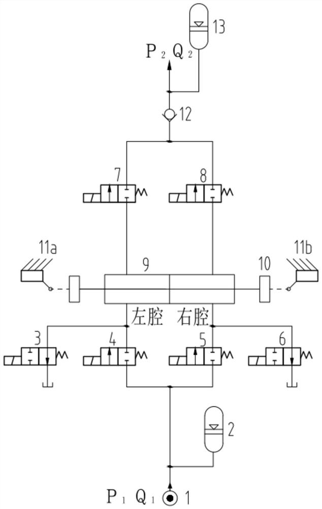
[0033] Such as figure 1 As shown in the figure, a high-speed switch valve-controlled hydraulic cylinder hydraulic transformer with large variable pressure range and continuous variable pressure includes a hydraulic cylinder 9, which is divided into a left cavity and a right cavity, and the two ends of the piston rod of the hydraulic cylinder 9 have mass blocks. The piston, the piston rod and the two mass blocks together form the mass block piston rod 10, and travel switches (11a, 11b) are respectively arranged at the end of strokes on the left and right sides of the mass block piston rod 10, when the mass block piston rod 10 reaches the left or right Trigger the limit switch at the end of the stroke.

[0034] The oil outlet of the high-speed on-off valve 4 is connected to the left chamber, the oil outlet of the high-speed on-off valve 5 is connected to the right chamber, and the oil inlet of the high-speed on-off valve 4 and the high-speed on-off valve 5 are connected to each ...

Embodiment 2

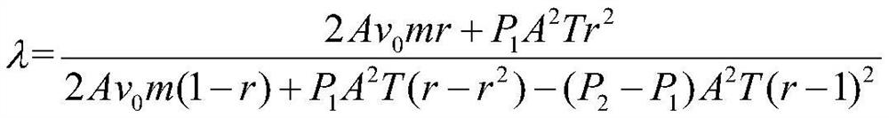
[0057] Suppose hydraulic source 1 provides pressure P 1 and flow Q 1 , the pressure supplied to the load is P 2 , the flow rate is Q 2 , the cross-sectional area of ​​the piston rod 10 of the mass block is A, one period of the PWM control signal is T, the mass of the piston rod 10 of the mass block is m, the length of the hydraulic cylinder 9 is L, and the initial velocity of the piston rod 10 of the mass block is v 0 . Wherein, if the mass m of the mass block piston rod 10 is large, its velocity will be very small in the working condition where the hydraulic energy is converted into kinetic energy, and the displacement will be small in the same period, resulting in the flow rate Q 2 is very small; if the mass m of the mass block piston rod 10 is very large, its speed will be very high, and in the same period, the displacement will be very large, which will easily lead to the inability to complete a working condition within the length L of the hydraulic cylinder 9, so m Th...


PUM


Abstract

The invention provides a continuous transformation large-transformation-range hydraulic transformer for a high speed valve-controlled hydraulic cylinder. The transformer comprises a hydraulic oil cylinder; mass blocks are arranged at two ends of a piston rod of the hydraulic oil cylinder; the piston rod and the mass blocks constitute a mass block piston rod; and stroke switches are respectively arranged at stroke ends on the left and the right of the mass block piston rod. Through the combination of a one-way valve and a high-speed switch valve, flow direction of oil liquid is controlled, andwith the addition of an energy accumulator, continuous flow borne by flow direction of the one-way valve is realized. The integral structure is laterally symmetrical; the pressurization process and the depressurization process are functionally theoretically symmetrical; forward pressurization and reverse pressurization in the pressurization process are functionally theoretically symmetrical; and forward depressurization and reverse depressurization in the depressurization process are functionally theoretically symmetrical. Through the mutual conversion of hydraulic energy and kinetic energy ofthe mass block piston rod, continuous stepless transformation can be realized on the premise that the structure of a hydraulic cylinder is unchanged; a required hydraulic transformation ratio can beobtained through adjusting the duty ratio of a PWM signal; and the control is convenient, the structure is simple, and zero vibration or noise is realized.

Description

technical field [0001] The invention relates to the field of hydraulic transmission and control, in particular to the field of hydraulic engineering machinery, in particular to a hydraulic transformer with continuous variable pressure, large variable voltage range, and high-speed switching valve-controlled hydraulic cylinder. Background technique [0002] The pressurized hydraulic cylinder is a commonly used hydraulic component in the existing hydraulic technology. The pressurized hydraulic cylinder can achieve the effect of pressurization or decompression by utilizing the difference in the cross-sectional area of ​​the piston or plunger in the two cylinders connected in series on the same axis. The disadvantage of the supercharged hydraulic cylinder's own structure is that its piston area ratio is fixed, that is, its transformation ratio remains unchanged, so that it cannot achieve continuous stepless pressure transformation effect, resulting in serious restrictions on its a...

Claims


Application Information

Patent Timeline
Patent Type & Authority Applications(China)
IPC IPC(8): F15B1/02F15B3/00F15B15/22
CPCF15B1/024F15B3/00F15B15/22
Inventor 周连佺薄晓楠张楚刘强杜文芳
Owner XUZHOU NORMAL UNIVERSITY
Why Eureka
Try Eureka