Reagent bottle cleaning and sterilizing equipment for genetic engineering
A technology of cleaning and disinfection and genetic engineering, applied in the field of genetic engineering, can solve the problems of cleaning and disinfection of the inner wall of difficult reagent bottles and low efficiency
- Summary
- Abstract
- Description
- Claims
- Application Information
AI Technical Summary
Problems solved by technology
Method used
Image


Examples
Embodiment 1
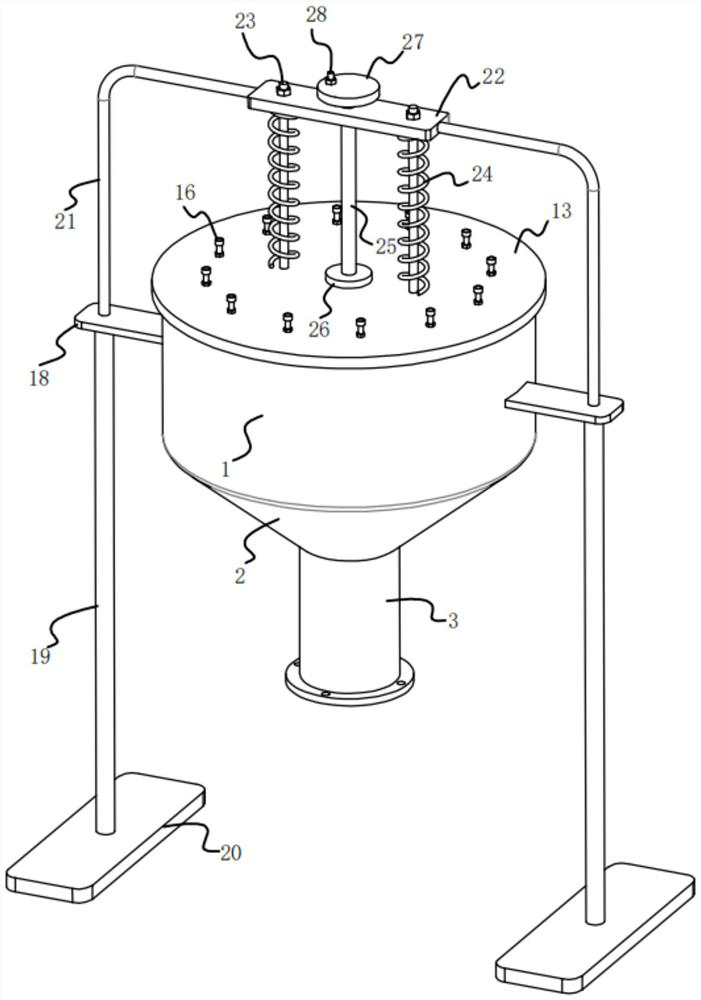
[0023] refer to Figure 1-6 , a reagent bottle cleaning and disinfection equipment for genetic engineering, comprising a cylinder 1, the bottom end of the cylinder 1 is fixedly installed with a conical bucket 2 communicating with the inside, and the bottom of the conical bucket 2 is fixedly installed with a cone connected to the inside The pipe body 3, and the cylinder body 1, the tapered bucket 2, and the pipe body 3 are coaxially arranged, and a horizontal plate 4 is fixed inside the pipe body 3, and a rotating shaft 5 is rotatably installed on the horizontal plate 4, and the bottom end of the rotating shaft 5 is fixedly installed There is an impeller 6, and the top of the rotating shaft 5 extends upward until it extends into the cylinder 1. A cleaning module is fixedly installed in the cylinder 1. The rotating shaft 5 is connected to the cleaning module by transmission. The outer surface of the lower part of the cylinder 1 is fixed along the circumferential direction. There...
Embodiment 2
[0029] refer to Figure 1-4 , as another preferred embodiment of the present invention, the difference from Embodiment 1 is that the cover body opening and closing module includes a support bent rod 21, a top plate 22, a threaded rod 23, a spring 24, a top column 25, and two side plates 18 A supporting curved rod 21 is fixedly installed on the upper surface, and two supporting curved rods 21 are arranged correspondingly, and a top plate 22 is fixedly installed between the upper inner ends of the two supporting curved rods 21, and two threaded rods are installed through the top plate 22 23. The bottom ends of the two threaded rods 23 are fixedly installed on the top cover 13, and a limit nut is installed on the threaded rods 23 above the top plate 22, and the threaded rods 23 between the top plate 22 and the top cover 13 are sleeved. There is a spring 24, and the two ends of the spring 24 are respectively fixedly connected to the corresponding top plate 22 and the top cover 13,...
PUM
 Abstract
Description
Claims
Application Information
PatSnap Eureka turns technology decisions into work you can execute. Powered by our Innovation Knowledge Graph, it runs expert workflows across engineering, life sciences, materials and intellectual property. Get your review-ready output in minutes.


