
Heat-dissipating laser marking system with angle adjusting function

A technology of laser marking and angle adjustment, which is applied to laser welding equipment, manufacturing tools, welding equipment, etc., can solve the problems of reducing the efficiency of workers loading and unloading, inconvenient use, and inconvenient opening and use, so as to improve the marking speed of the system , Improve the marking speed and optimize the operability of the equipment

Pending Publication Date: 2020-09-29
天津镭恒自动化科技有限公司
View PDF0 Cites 0 Cited by
  • Summary
  • Abstract
  • Description
  • Claims
  • Application Information

AI Technical Summary

Problems solved by technology

However, the loading station, unloading station and marking work of this kind of equipment are all at the same height, so the size of this kind of equipment is particularly large, and the loading and unloading stations are generally on both sides of the marking station, which is also Reduced loading and unloading efficiency of workers
Moreover, the protective parts of all existing equipment are fixed, which is very inconvenient to use and inconvenient to open and use.

Method used


Image

  • Heat-dissipating laser marking system with angle adjusting function
  • Heat-dissipating laser marking system with angle adjusting function

Examples


Embodiment 1

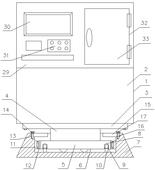
[0019] A heat-dissipating laser marking system with an angle adjustment function, which consists of: a manual loading and unloading and automatic loading and unloading FPC marking equipment body 1 (being the prior art), and the manual loading and unloading and automatic loading and unloading FPC marking equipment body has The lower box 2, the bottom of the lower box is connected to the bottom disc 3 and fixed by screws, the bottom disc is fixedly connected to the bottom pillar 4, and the bottom pillar is fixedly connected to the rotary disc 5, the The rotating disk is installed in the ring groove 6, and the rotating disk can rotate freely in the ring groove, which is convenient for manual loading and unloading and automatic loading and unloading. In the base 7, an inverted U-shaped annular groove 8 is opened on the bottom of the rotating disc, and the annular groove is connected with a group of shafts 9 around the circumference, and the shaft is connected with a round wheel 10 ...

Embodiment 2

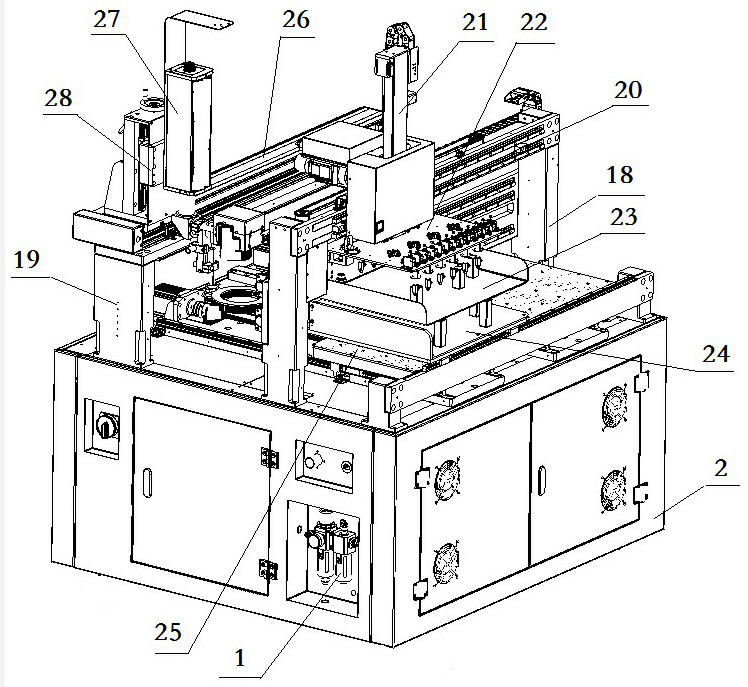
[0023] A heat-dissipating laser marking system with an angle adjustment function described in Embodiment 1, the FPC marking equipment body with manual loading and unloading and automatic loading and unloading has a front bracket 18 and a rear bracket 19, and the front bracket is connected to the feeding Horizontal moving shaft 20, the described horizontal moving shaft for retrieving is connected to the vertical moving shaft 21 for use, the vertical moving shaft for retrieving is connected to the retrieving suction cup 22, and the described suction cup for retrieving corresponds to the blanking station 23, so The bottom of the blanking station is provided with a loading station 24, and the bottom of the loading station is provided with a marking station 25. The rear support is connected to the laser automatic horizontal movement axis 26, and the automatic horizontal movement of the laser is The mobile axis connects the laser 27 and the laser manually adjusts the vertical axis 28...


PUM


Abstract

The invention relates to a heat-dissipating laser marking system with an angle adjusting function. A product comprises a manual loading and unloading an automatic loading and unloading FPC marking equipment body which is provided with a lower box body, wherein the bottom of the lower box body is connected to a bottom disc and is fixed through a screw; the bottom disc is fixedly connected to a bottom supporting column; the bottom supporting column is fixedly connected to a rotary disc; the rotary disc is mounted in a ring slot; the ring slot is formed in a base; a reversed U-shaped ring grooveis formed in the bottom of the rotary disc; a group of shaft levers is connected around the circumference of the ring groove; the shaft levers are connected to a round wheel; the round wheel rotates circumferentially around the ring slot; the ring groove is connected to an inner gear ring; the rotary disc is in connection and engagement to a positioning gear; and the positioning gear is engaged with the inner gear ring to position. The heat-dissipating laser marking system is used as an environmental-friendly laser marking system.

Description

Technical field: [0001] The invention relates to a heat dissipation laser marking system with angle adjustment function. Background technique: [0002] At present, the existing FPC laser marking system is divided into two types: manual loading and unloading and automatic loading and unloading. However, both types of equipment are fixed and supported, and it is very inconvenient to go back and forth to each surface during operation. If the installation is in a narrow space, the operation will be even more inconvenient. [0003] Among them, manual loading and unloading needs to manually place the flexible circuit board on the equipment fixture, and then the worker starts the laser for laser marking. The loading and unloading work of each piece of flexible circuit board of this kind of equipment requires workers to manually carry out, so the degree of automation of this kind of equipment is low, the manual labor is large, and the production efficiency is low. In addition, the...

Claims


Application Information

Patent Timeline
IPC IPC(8): B23K26/362B23K26/70
CPCB23K26/362B23K26/702
Inventor 张帅李树勇田红伟
Owner 天津镭恒自动化科技有限公司
Learn More