Workpiece pushing mechanism, netting machine and evaporation system
A workpiece and component technology, applied in the field of workpiece pushing mechanism, net stretcher and evaporation system, can solve the problems of complex structure, high cost, large space occupied by net stretcher, etc., to improve motion resolution and reduce occupation Space and cost reduction effects
- Summary
- Abstract
- Description
- Claims
- Application Information
AI Technical Summary
Problems solved by technology
Method used
Image
Examples
Embodiment 1
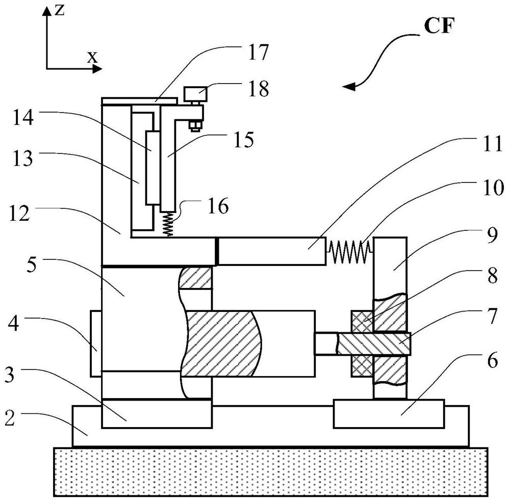
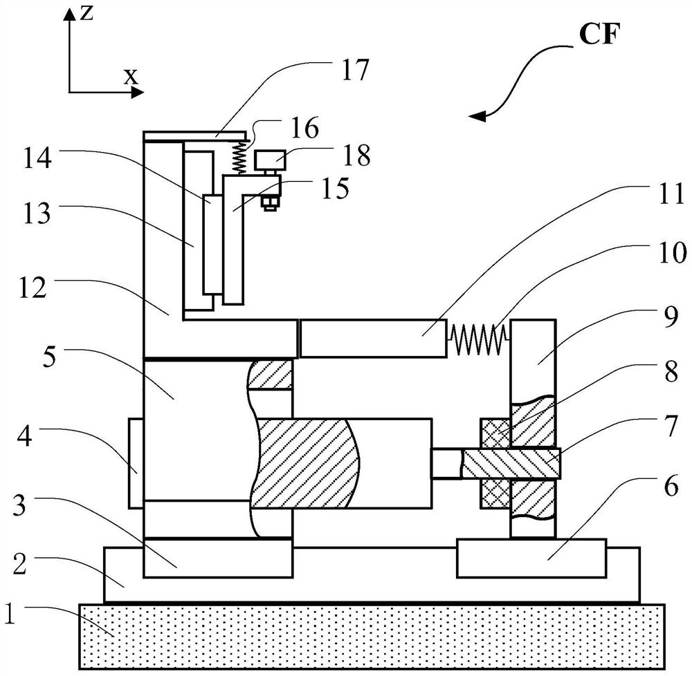
[0041] Please refer to figure 1 , the present embodiment provides a workpiece pushing mechanism CF, including a base body 1, a horizontal driving unit, a vertical driving unit, a clamping unit and a measuring unit. Wherein, the horizontal drive unit includes a horizontal guide part 2, a motor 4, a horizontal movement assembly mainly composed of a first horizontal movement part 6 and a first horizontal movement terminal 9, a second horizontal movement part 3, a second horizontal movement terminal 5. Buffer spring 10; the clamping unit includes a support base 12 and a clamper, the clamper includes a limiter 17 and a roller 18, and the roller 18 can realize the decoupling of the Rz degree of freedom of the workpiece when clamping the workpiece The vertical drive unit is a mechanical device driven by gravity and elastic force, including a vertical guide component 13 , a vertical moving component 14 , a vertical movement terminal 15 and a vertical elastic reset component 16 . The ...
Embodiment 2
[0056] In order to be compatible with the accurate measurement of the workpiece position, that is, to be able to determine the X or Y coordinates and Rz of the workpiece, this embodiment provides a workpiece pushing mechanism, which is compatible with figure 1 Compared with the workpiece pushing mechanism in the first embodiment shown, a grating scale sensor (not shown) is added to the measuring unit, and the grating scale sensor includes a grating main scale (not shown) and a reading head (not shown). Show). The grating main ruler can be arranged on the ball 18, the first moving terminal 9, the first moving part 6, the second moving part 3, the second moving terminal 5, the support seat 12, the pressure sensor 11 or the vertical guide part 13, so The reading head can be arranged on the base body 1 or the horizontal guide part 2 or the motor 4, the reading head is fixed relative to the motor 4 and the base body 1, and the parallelism between the reading head and the grating ma...
Embodiment 3
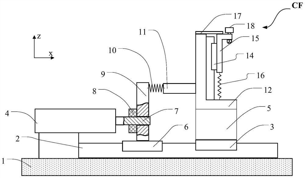
[0060] Please refer to figure 2 , when the horizontal space permits, this embodiment provides a workpiece pushing mechanism, which is compatible with figure 1 Compared with the workpiece pushing mechanism in the first embodiment shown, the motor 4 and the second moving terminal 5 are no longer nested together, specifically, the second moving terminal 5 is arranged on the side of the first moving terminal 9 facing away from the motor 4 side. The pressure sensor 11 can be fixedly connected to the vertical bracket of the support base 12 , or can be fixedly connected to the second moving terminal 5 .
[0061] In addition, since other parts of the workpiece pushing mechanism of this embodiment can be combined with figure 1 The corresponding parts of the workpiece pushing mechanism in the first embodiment shown are completely the same, therefore, these structures will not be repeated in this embodiment.
[0062] In the workpiece pushing mechanism of this embodiment, since the mo...
PUM
 Abstract
Description
Claims
Application Information
 - R&D
- Intellectual Property
- Life Sciences
- Materials
- Tech Scout
- Unparalleled Data Quality
- Higher Quality Content
- 60% Fewer Hallucinations
Browse by: Latest US Patents, China's latest patents, Technical Efficacy Thesaurus, Application Domain, Technology Topic, Popular Technical Reports.
© 2025 PatSnap. All rights reserved.Legal|Privacy policy|Modern Slavery Act Transparency Statement|Sitemap|About US| Contact US: help@patsnap.com


