Muck drainage pond structure and pressure difference electromagnetic field coupling drainage method for muck

A drainage pond and muck technology, which is applied in drainage structures, soil protection, water/sewage treatment, etc., can solve the problems of high investment cost and operating cost, no space for placing the whole set of equipment, and limited construction site space. Enhanced effect, less clogging, faster drainage

Pending Publication Date: 2020-09-29
HUNAN UNIV OF SCI & ENG
View PDF0 Cites 1 Cited by
  • Summary
  • Abstract
  • Description
  • Claims
  • Application Information

AI Technical Summary

Problems solved by technology

[0013] 1. High investment cost. Centrifuges and filter presses are large-scale equipment with high initial investment costs and high operating costs;
[0014] 2. The equipment occupies a large area. The starting position and slag outlet of shield tunneling are generally set at subway stations, and subway stations are generally located near road intersections. The space of the construction site is limited, and there is usually no space for placing the entire set of equipment;
[0015] 3. The processing efficiency is low, even with 1000m 2 The filter press can only process more than a dozen square meters of dry soil per hour, while the shield machine can excavate one ring every half an hour during normal construction, and the amount of muck generated can reach 60m 3 , so when the filter press is used for processing, a large amount of slag will be accumulated

Method used


Image

  • Muck drainage pond structure and pressure difference electromagnetic field coupling drainage method for muck
  • Muck drainage pond structure and pressure difference electromagnetic field coupling drainage method for muck

Examples


Embodiment Construction

[0041] The present invention will be further described below in conjunction with the accompanying drawings.

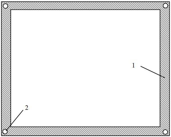
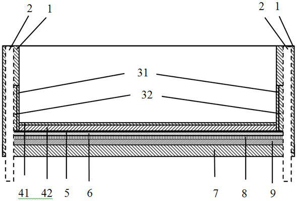
[0042] Such as Figure 1-2 As shown, the muck drainage pond structure of the present invention includes a muck drainage pond 1 and an electroosmosis control instrument. A water collection well 2, the water collection well 2 is vertically arranged. The well wall of the water collection well 2 is formed by placing ecological sand-based permeable bricks in the direction of the reverse filter layer. The side wall between the lower inner cavity of the muck drainage pond 1 and the water collection well is made of permeable material; the side wall between the lower inner cavity of the muck drainage pond 1 and the water collection well 2 includes a permeable layer I31 and Water-permeable layer II32 and water-permeable layer I31 are located inside water-permeable layer II32. Water-permeable layer I31 is made of micronano-scale water-permeable resin sand, and water-permeable l...


PUM

PropertyMeasurementUnit
Particle sizeaaaaaaaaaa

Abstract

The invention discloses a muck drainage pond structure and a pressure difference electromagnetic field coupling drainage method for muck. The muck drainage pond structure comprises a muck drainage pond and an electroosmotic control instrument; a plurality of water-collecting wells are formed in the side wall of the muck drainage pond, and the water-collecting wells are vertically formed; an innercavity in the lower part of the muck drainage pond and the side walls between the water-collecting wells are made of pervious materials; a bottom plate of the muck drainage pond sequentially comprisesa reverse-filter pervious bottom plate, a rust-proof steel wire gauze layer, a filter geotechnical cloth layer, a water storage and draining plate and a reinforced concrete bottom plate from top to bottom; a blind ditch is formed in the reinforced concrete bottom plate and communicates with the water-collecting wells; the electroosmotic control instrument is connected with a steel chisel and therust-proof steel wire gauze layer; and the steel chisel is used for being inserted into the muck. The muck drainage pond structure is simple, and the one-time input and operation costs are low; expensive treatment equipment does not need to be used, the cost is lowered, and the treatment efficiency of the muck is high; and the one-time muck treatment volume has no upper limit.

Description

technical field [0001] The invention belongs to the technical field of slag treatment, and in particular relates to a slag drainage pool structure and a pressure difference electromagnetic field coupling drainage method of the slag. Background technique [0002] The construction of rail transit has promoted the development of urban economy, solved the problem of urban traffic congestion, and improved the travel conditions of the people, but it has also brought a series of environmental and safety problems. Outstanding issue. [0003] The subway is generally divided into station and section construction, and the section construction usually adopts the shield method. The shield muck is mostly fine particles with high moisture content, which is more harmful than the muck produced by drilling and blasting and other mechanical excavation methods. [0004] First of all, in the process of muck transportation, various environmental and safety problems often occur, such as environm...

Claims


Application Information

Patent Timeline
IPC IPC(8): E03F5/10E03F5/14E02D3/11
CPCE02D3/11E03F5/10E03F5/101E03F5/105E03F5/14
Inventor 李仁平周基郭华
Owner HUNAN UNIV OF SCI & ENG
Why Eureka
Try Eureka