Supercharge Your Innovation With Domain-Expert AI Agents!

High-strength airflow uniform distribution plate and desulfurizing tower

A high-strength technology with uniform airflow distribution plate, which can be used in gas treatment, use of liquid separation agents, membrane technology, etc., and can solve problems such as easy fire.

Pending Publication Date: 2020-10-02
CHINA HUADIAN ENG +1
View PDF0 Cites 1 Cited by
  • Summary
  • Abstract
  • Description
  • Claims
  • Application Information

AI Technical Summary

Problems solved by technology

[0006] Therefore, the technical problem to be solved by the present invention is to overcome the defects in the prior art that the tray structure needs to be welded and installed inside the desulfurization tower, which is easy to cause fire, thereby providing a new type of high-strength tray and desulfurization tower

Method used


Image

  • High-strength airflow uniform distribution plate and desulfurizing tower
  • High-strength airflow uniform distribution plate and desulfurizing tower
  • High-strength airflow uniform distribution plate and desulfurizing tower

Examples


Embodiment 1

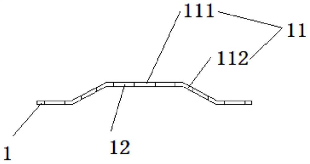
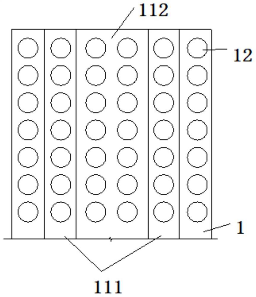
[0051] The invention provides a high-strength air distribution plate, such as figure 1 , figure 2 As shown, it includes: a base plate 1 provided with a number of ventilation holes 12 ; a reinforcement structure 11 provided on the base plate 1 and protruding outward relative to the base plate 1 . On the one hand, the outwardly protruding reinforcement structure 11 can improve the strength of the airflow uniform distribution plate itself, and can also increase the surface area of ​​the airflow uniform distribution plate, increase the opening area, and improve the efficiency of smoke passing through. The air flow uniform distribution plate is usually below the wet dust removal mechanism 5, and performs flow equalization treatment on the flue gas before the flue gas is subjected to wet dust removal. The air flow uniform distribution plate with the reinforced structure 11, because the reinforced structure 11 protrudes relatively outward, the area receiving spray increases, and mo...

Embodiment 2

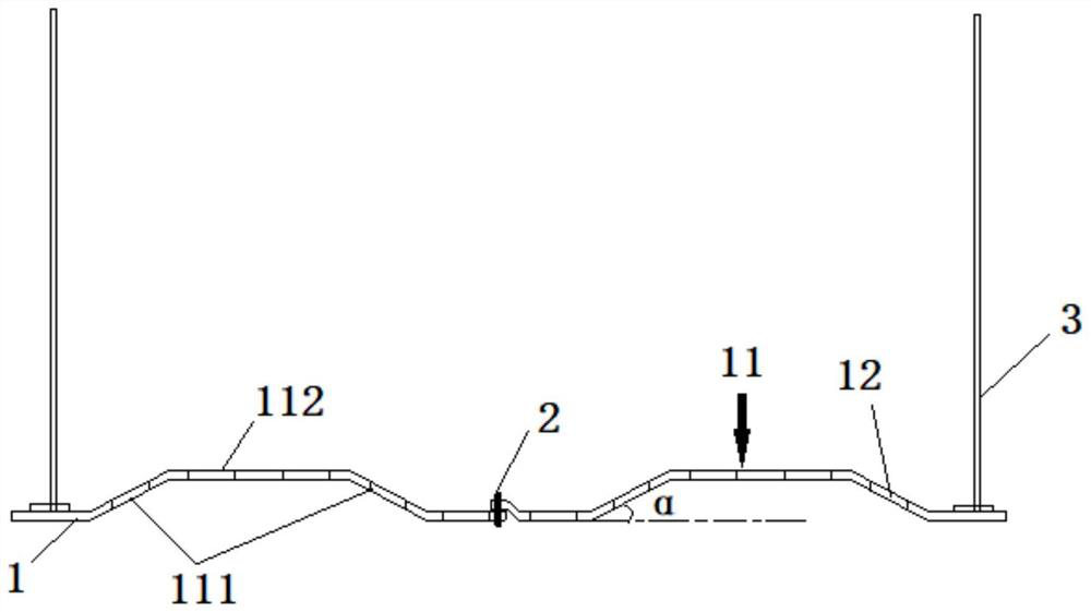
[0057] The present invention also provides a desulfurization tower, such as Figure 4 As shown, it includes: a wet dust removal mechanism 5, which is correspondingly arranged in the channel for flue gas flow in the desulfurization tower; The air flow uniform distribution plate with the reinforced structure 11, because the reinforced structure 11 protrudes relatively outward, the area receiving spray increases, and more spray liquid adheres to the air flow uniform distribution plate, which improves the spray liquid and smoke Air contact area and contact efficiency, thus enhancing the effect of wet dust removal.

[0058] On the basis of the above embodiments, as a further limited embodiment, such as Figure 4 As shown, the desulfurization tower also includes: a variable diameter section 4, which is located below the wet dust removal mechanism 5, and the cross-sectional area of ​​the flue gas flow channel is within the scope of the variable diameter section 4. The direction of ...


PUM


Abstract

The invention provides a high-strength airflow uniform distribution plate and a desulfurization tower. The high-strength airflow uniform distribution plate comprises: a substrate provided with a plurality of air holes; and a reinforcing structure arranged on the substrate and protrudes outwards relative to the substrate. On one hand, the outwards-protruding reinforcing structure can improve the strength of the airflow uniform distribution plate, increase the surface area of the airflow uniform distribution plate, increase the hole area and improve the smoke passing efficiency. And the airflowuniform distribution plate is generally arranged below a wet dust removal mechanism, and is used for carrying out flow equalization treatment on the flue gas before the wet dust removal of the flue gas. According to the airflow uniform distribution plate with the reinforcing structure, due to the fact that the reinforcing structure protrudes outwards relatively, the spraying area is increased, more spraying liquid is attached to the airflow uniform distribution plate, the contact area and the contact efficiency of the spraying liquid and flue gas are improved, and the wet dust removal effect is enhanced.

Description

technical field [0001] The invention relates to the technical field of flue gas desulfurization and denitrification equipment structure, in particular to a high-intensity airflow uniform distribution plate and a desulfurization tower. Background technique [0002] Thermal power plants will produce a lot of flue gas during operation, which contains sulfur and other pollutants. Therefore, there are strict emission standards for flue gas emissions from thermal power plants. With the gradual strengthening of environmental protection awareness, the emission requirements of thermal power plants are getting higher and higher. The desulfurization tower is one of the flue gas treatment equipment in thermal power plants. The flue gas can be treated more efficiently and harmlessly. [0003] The air flow uniform distribution plate is an important structure in the desulfurization tower. The air flow uniform distribution plate has vent holes. When the flue gas moves from bottom to top in...

Claims


Application Information

Patent Timeline
Patent Type & Authority Applications(China)
IPC IPC(8): B01D53/78B01D53/48B01D47/06
CPCB01D53/78B01D53/48B01D47/06B01D2258/0283
Inventor 夏怀鹏吴冲王凯亮汪洋赵冰王争荣
Owner CHINA HUADIAN ENG
Features
  • R&D
  • Intellectual Property
  • Life Sciences
  • Materials
  • Tech Scout
  • Unparalleled Data Quality
  • Higher Quality Content
  • 60% Fewer Hallucinations
Learn More