Industrial wastewater filtering and clarifying device

A clarification device and industrial wastewater technology, applied in the direction of filtration circuit, filtration separation, filtration treatment, etc., can solve the problems of slowing down the speed, reducing the filtering effect of the fence, etc., achieving obvious effects and suitable for promotion

Pending Publication Date: 2020-10-02
孟红海
View PDF0 Cites 5 Cited by
  • Summary
  • Abstract
  • Description
  • Claims
  • Application Information

AI Technical Summary

Problems solved by technology

[0004] The purpose of the present invention is to solve the shortcomings in the prior art that the vegetable leaves and fruit peels in the wastewater will be entangled and blocked on the fence, which will cause the speed of water flow through the fence to slow down, thereby reducing the filtering effect of the fence, and proposes an industrial wastewater filter. clarification device

Method used


Image

  • Industrial wastewater filtering and clarifying device
  • Industrial wastewater filtering and clarifying device
  • Industrial wastewater filtering and clarifying device

Examples


Embodiment 1

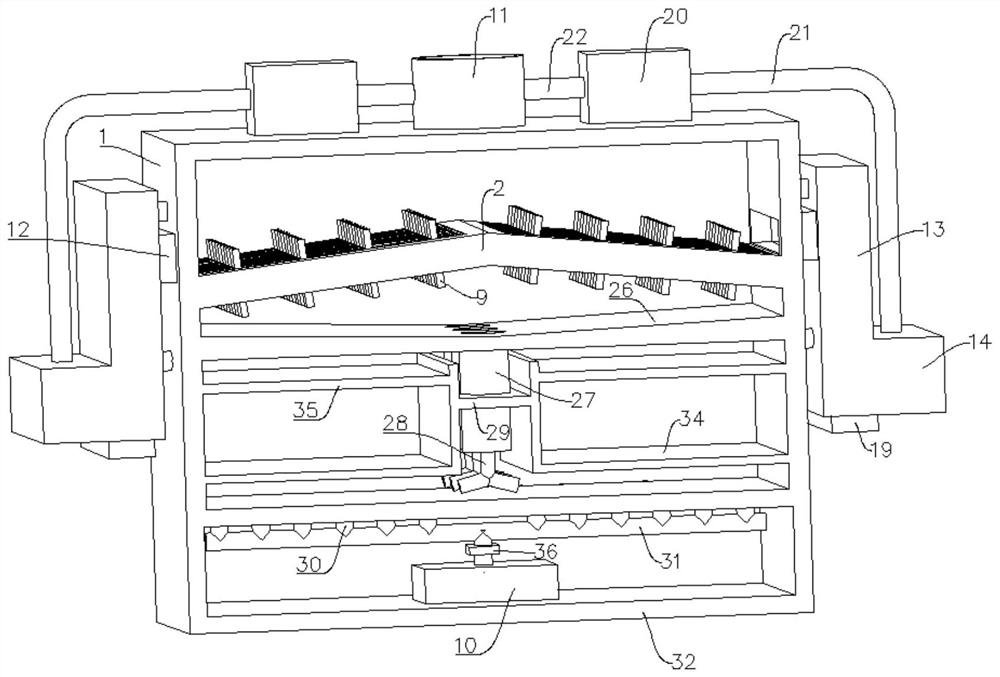
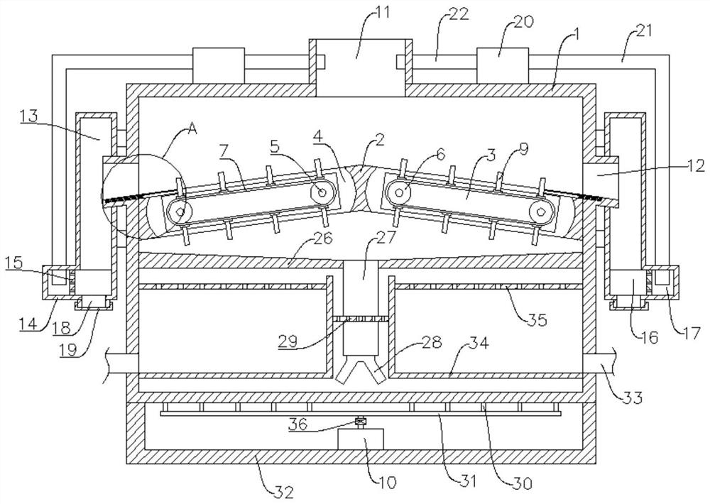
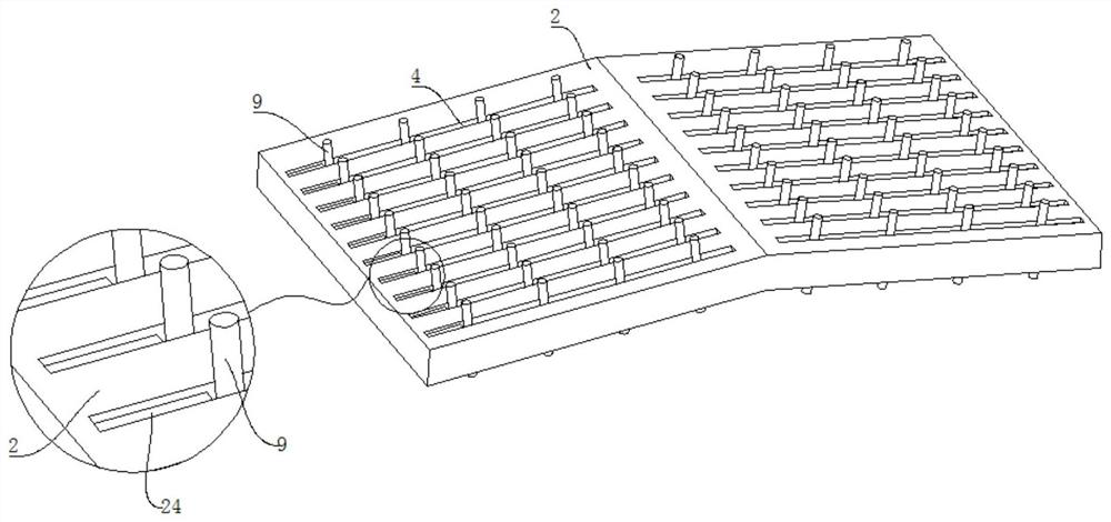
[0025] refer to Figure 1-8 , an industrial waste water filtration and clarification device, comprising a box body 1, the interior of the box body 1 is fixedly provided with a filter partition 2, the filter partition plate 2 divides the interior of the box body 1 into upper and lower parts, and the middle part of the filter partition plate 2 is convex and the two sides are slope-shaped, so that most of the solid waste on the filter partition 2 will roll to the two ends of the filter partition 2 under the action of its own gravity, and block the filter fence on the filter partition 2 The stagnation will be greatly reduced.

[0026] In the present invention, the interior of the filter partition 2 is provided with two square grooves 3 that are symmetrical about the center of the filter partition 2, and the side walls around the square groove 3 are provided with a plurality of equidistantly distributed through grooves 4 outward. 4 runs through the upper and lower sides of the fil...

Embodiment 2

[0030] In embodiment 1, the solid waste staying at both ends of the filter partition 2 will gradually accumulate and accumulate on the filter partition 2. If these solid wastes are not removed in time, when the solid waste accumulates too much, even if there is a toggle lever 9 Even if the waste is moved, the waste cannot be pushed to both ends of the filter partition 2. These solid wastes will gradually cover the through groove 4 and affect the filtering effect of the filter partition 2. Refer to figure 1 and 2 , as another preferred embodiment of the present invention, the difference from Embodiment 1 is that a sewage outlet 12 is provided on the side wall of the box body 1 corresponding to the two lowest ends of the filter partition 2, and the bottom of the sewage outlet 12 is downward Inclined and the same as the inclination angle of the filter partition 2, the sewage outlet 12 connects the inside and the outside of the box body 1, and the solid waste accumulated at both e...

Embodiment 3

[0032] In Embodiment 2, by setting the sewage outlet 12, solid waste can be discharged through the sewage outlet 12, but at this time part of the waste water will also be discharged through the sewage outlet 12. If the waste water discharged through the sewage outlet 12 is directly discharged, since there is no In the later stage of secondary treatment and tertiary treatment, the wastewater contains a large amount of other substances to be treated, which will seriously affect the environment. Refer to figure 1 and 2 As another preferred embodiment of the present invention, the difference from Embodiment 2 is that a collection box 13 is fixedly arranged on the outer wall of the box body 1 through a connecting rod, and the sewage outlet 12 extends through the collection box 13 to the inside of the collection box 13, The collection box 13 and the sewage outlet 12 are airtightly arranged, and the bottom end of the collection box 13 is fixedly provided with a separation box 14, and...


PUM


Abstract

The invention relates to the technical field of industrial wastewater treatment, and especially relates to an industrial wastewater filtering and clarifying device. The device comprises a box body, wherein a filtering clapboard is fixedly arranged in the box body; the interior of the box body is divided into an upper part and a lower part by the filtering clapboard; the middle part of the filtering clapboard is raised, and two sides are arranged in a slope shape; two square grooves which are symmetrical about the center of the filtering clapboard are formed in the filtering clapboard; a plurality of through grooves which are distributed at equal intervals are outwards formed in the peripheral side walls of the square grooves; the through grooves penetrate through the upper face and the lower face of the filtering clapboard; the edges, located in the filtering clapboard, of the through grooves are arranged in an arc shape; two rotating shafts are arranged in the square grooves; the twoends of each rotating shaft are rotationally arranged on the inner wall of the box body through bearings; and the rotating shafts are perpendicular to the through grooves. The problem that in the prior art, vegetable leaves and peels in wastewater are wound and blocked on a fence, so that the speed of water flowing through the fence is decreased, and the filtering effect of the fence is reduced issolved, and the beneficial effect is obvious.

Description

technical field [0001] The invention relates to the technical field of industrial wastewater treatment, in particular to an industrial wastewater filtration and clarification device. Background technique [0002] The food industry has a wide range of raw materials and a wide variety of products. The amount and quality of wastewater discharged vary greatly. The main pollutants in wastewater include solid substances suspended in wastewater, such as vegetable leaves, fruit peels, minced meat, poultry feathers, etc.; suspended in wastewater Substances include oil, protein, starch, colloidal substances, etc.; acids, alkalis, salts, sugars, etc. dissolved in wastewater; mud sand and other organic matter entrained in raw materials; pathogenic bacteria and viruses, etc. Food industry wastewater is characterized by high content of organic matter and suspended matter, easy to be corrupted, and generally has no great toxicity. The main hazard is to eutrophicate the water body, causing ...

Claims


Application Information

Patent Timeline
Patent Type & Authority Applications(China)
IPC IPC(8): C02F9/02B01D36/04
CPCB01D36/04C02F1/001C02F1/52C02F2201/002C02F2301/08C02F2303/14C02F2303/16
Inventor 不公告发明人
Owner 孟红海
Why Eureka
Try Eureka