Conical barrel supporting body used for anchor bolt and anchor bolt

A technology of bearing body and anchor rod, which is applied in the direction of installing anchor rods, sheet pile walls, mining equipment, etc., can solve the problems of small bearing area, small pull-out resistance, and low mechanical strength, and achieve pull-out resistance of anchor rods The effects of increased force, improved pull-out resistance, and improved mechanical strength

Pending Publication Date: 2020-10-02
深圳钜联锚杆技术有限公司
View PDF8 Cites 3 Cited by
  • Summary
  • Abstract
  • Description
  • Claims
  • Application Information

AI Technical Summary

Problems solved by technology

The bearing surface is perpendicular to the central axis of the bolt body, the load-bearing area of ​​the bearing surface is small, the force of the grouting body is controlled by the unidirectional axial compressive strength, and the mechanical strength is low. Small pulling force

Method used


Image

  • Conical barrel supporting body used for anchor bolt and anchor bolt
  • Conical barrel supporting body used for anchor bolt and anchor bolt
  • Conical barrel supporting body used for anchor bolt and anchor bolt

Examples


Embodiment 1

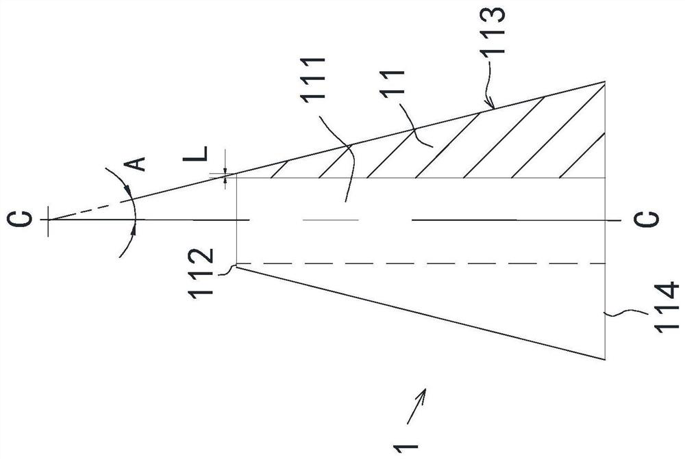
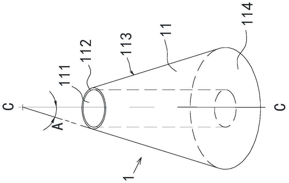
[0070] Such as Figures 1A-1B , figure 2 As shown, the present embodiment 1 provides a conical tube carrier 1, which is formed by a tube wall 11 surrounded by a tube wall 11 to form a central hole 111, the central hole 111 is a straight-through light hole, The hole diameter is slightly larger than the outer diameter of the rod body 2 of the anchor rod, and the diameter difference is less than 4mm. The rod body 2 of the anchor rod penetrates the central hole 111, so that the cone carrier 1 is sleeved on the rod body 2 of the anchor rod.

[0071] In this embodiment, the cross section of the top 112 and the bottom 114 of the cylinder wall 11 is a hollow circle, the conical surface 113 is a conical surface surrounding the central hole 111, and the included angle A between the conical surface and the axis C-C of the central hole 111 is 10° , the cone carrier body 1 has a cone structure.

[0072] In this embodiment, the wall thickness L of the cylinder wall top 112 is 2 mm. The t...

Embodiment 2

[0074] see Figure 4 , Figure 5 , The second embodiment provides a conical cylinder carrier 1, including a cylinder wall 11, the cylinder wall 11 is a conical cylinder structure, and the external structure is consistent with the first embodiment. The difference from Embodiment 1 is that in this embodiment, the inner thread 1111 is processed on the wall of the central hole 111, which matches the outer thread on the rod body 2 of the anchor rod, and is used as the cone carrier 1 and the anchor rod. The connecting structure between the rod bodies 2 makes the cone carrier body 1 occluded and connected to the rod body 2 of the anchor rod.

[0075] In this embodiment, the cone carrier 1 has an internal thread 1111 on the wall of the central hole 111, so no welding equipment is needed during on-site construction, and the cone carrier 1 can be directly screwed to the position set by the rod body 2 of the anchor rod. Easy to operate.

Embodiment 3

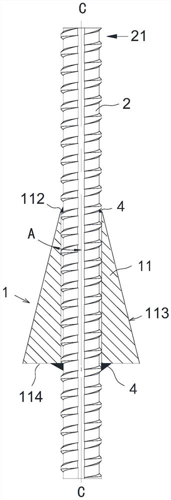
[0077] see Figures 6A-6B , a conical cylinder carrier 1 provided in the third embodiment, the conical cylinder carrier is formed by the cylinder wall 11, the central hole 111 formed after the cylinder wall 11 is surrounded is a straight through light hole, and the rod body 2 of the anchor rod passes through into the central hole 111, and the cone bearing body 1 is set on the rod body 2 of the anchor rod. Different from Embodiments 1 and 2, the cross-sections of the top 112 and bottom 114 of the cylinder wall in this embodiment are both hollow hexagons, and the conical surface 113 is a hexagonal conical surface surrounding the central hole 11. The conical cylinder carrier 1 It has a hexagonal pyramid structure, and the included angle A between the cone surface 113 and the axis C-C of the central hole 111 is about 15°. On the plane where the top 112 and bottom 114 of the cylinder wall meet the rod body 2 of the anchor rod, weld seams 4 are piled up, and the cone carrier 1 is f...


PUM


Abstract

The invention provides a conical barrel supporting body used for an anchor bolt. The conical barrel supporting body is formed by a barrel wall in a surrounding mode. A central hole formed by the barrel wall in the surrounding mode adapts to a bolt body of the anchor bolt, and is used for sleeving the bolt body of the anchor bolt. The barrel wall is provided with a top, a bottom and an outer wall surface, wherein the outer diameter of the top is smaller than that of the bottom, the outer wall surface is a conical surface, and an included angle formed between the conical surface and the axis ofthe central hole is smaller than 45 degrees. The invention further provides the anchor bolt. The anchor bolt comprises the bolt body of the anchor bolt and the conical barrel supporting body mounted on the bolt body. The top of the conical barrel supporting body faces the front end of the bolt body. The conical surface faces the eye wall of an anchor eye. According to the conical barrel supportingbody and the anchor bolt provided by the invention, when the anchor bolt is stretched, the conical surface on the conical barrel supporting body can extrude a grouting body towards the eye wall of the anchor eye along the normal of the conical surface by moving around the axis of the bolt body of the anchor bolt by 360 degrees, positive pressure is produced between the grouting body and the eye wall of the anchor eye, the positive pressure produces frictional resistance which is then converted into pulling resistance of the anchor bolt, the pulling resistance is greatly improved, the anchoring reliability is correspondingly improved, and the service life is also correspondingly prolonged.

Description

technical field [0001] The invention relates to the technical field of anchor rods, in particular to a cone bearing body for anchor rods and an anchor rod with the bearing body. Background technique [0002] Anchor rods are widely used in urban infrastructure construction such as housing construction, municipal engineering, and water conservancy, hydropower, transportation, railway, mining and other engineering constructions. [0003] In the technical field of bolts, as a tension member that directly penetrates into the formation, the pullout performance of the bolt is very important. Among the existing anchor rods, some anchor rods adopt a bearing body, the bearing body is installed on the rod body of the anchor rod, and the bearing surface of the bearing body adopts a plane perpendicular to the rod body of the anchor rod. The bearing surface is perpendicular to the central axis of the bolt body, the load-bearing area of ​​the bearing surface is small, the force of the gro...

Claims


Application Information

Patent Timeline
Patent Type & Authority Applications(China)
IPC IPC(8): E02D5/74E21D21/00
CPCE02D5/74E21D21/0026E21D21/0053E21D21/0033E02D2600/30E02D2600/20E02D2200/1692E02D2200/1657E02D2200/1607
Inventor 曾庆义
Owner 深圳钜联锚杆技术有限公司
Why Eureka
Try Eureka