
Connecting joint structure of rear steel longitudinal beam and old concrete cross beam and construction method

A technology for connecting nodes and concrete, applied in the direction of erecting/assembling bridges, bridges, bridge parts, etc., can solve the problem of lack of connection of concrete beams, and achieve the effect of improving the bearing capacity of longitudinal beam nodes, convenient construction and simple structure

Pending Publication Date: 2020-10-09
FUZHOU UNIVERSITY
View PDF0 Cites 0 Cited by
  • Summary
  • Abstract
  • Description
  • Claims
  • Application Information

AI Technical Summary

Problems solved by technology

The concrete beams in the suspension bridge system of this type of bridge lack connection. How to improve the structural comfort, anti-risk ability, and prolong the service life of the bridge are the key technical issues in the renovation project.

Method used


Image

  • Connecting joint structure of rear steel longitudinal beam and old concrete cross beam and construction method
  • Connecting joint structure of rear steel longitudinal beam and old concrete cross beam and construction method
  • Connecting joint structure of rear steel longitudinal beam and old concrete cross beam and construction method

Examples


Embodiment Construction

[0026] The present invention will be further described below in conjunction with the accompanying drawings and specific embodiments.

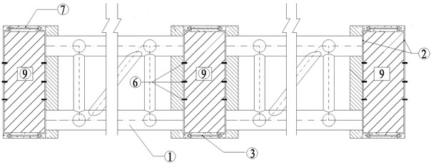
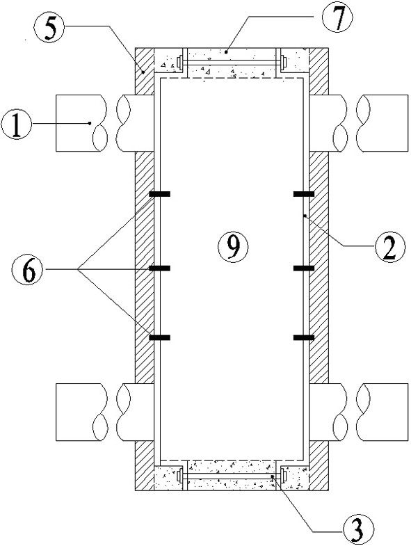
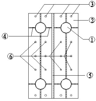
[0027] Such as Figure 1-4 As shown, a connection node structure between steel longitudinal beams and old concrete beams, including outsourcing steel plates 2, precision-rolled threaded steel bars 3, and implanted steel bars 6, and outsourcing steel plates are evenly distributed on both sides of the old concrete beams 9 along the longitudinal direction , the top edge and the bottom edge of the outsourcing steel plate are provided with a number of longitudinal through holes at intervals along the transverse direction, and the two ends of the fine-rolled threaded steel bar are pierced through the corresponding longitudinal through holes on both sides, and then the outsourcing steel plates on both sides are locked by nuts. The fine-rolled threaded steel bars are located outside the top and bottom edges of the old concrete beams, and a number of co...


PUM


Abstract

The invention relates to a connecting joint structure of a rear steel longitudinal beam and an old concrete cross beam and a construction method. The structure comprises outer wrapping steel plates, finish-rolled threaded steel bars and implanted steel bars; the outer wrapping steel plates are uniformly distributed outside the two longitudinal side surfaces of the old concrete cross beam; a plurality of longitudinal through holes are formed in the top edges and the bottom edges of the outer wrapping steel plates at intervals in the transverse direction; the two ends of finish-rolled twisted steel penetrate out of the corresponding longitudinal through holes in the two sides respectively and then lock and fix the outer wrapping steel plates on the two sides through nuts; a plurality of barplanting holes are formed in the middle of each outer wrapping steel plate; drill holes coaxial with the bar planting holes are formed in the bar planting holes in the old concrete cross beam; the inner ends of the implanted steel bars penetrate through the bar planting holes and are inserted into the drill holes; the end of the rear steel longitudinal beam is welded to the outer side faces of theouter wrapping steel plates, epoxy mortar layers are poured on the top edge and the bottom edge of the old concrete cross beam for filling and leveling up, and the finish-rolled threaded steel bars are wrapped in the epoxy mortar layers. The joint structure is convenient to construct, the rear steel longitudinal beam, the outer wrapping steel plates and the old concrete cross beam are jointly stressed, and the bearing capacity of the longitudinal and transverse beam joint can be improved.

Description

technical field [0001] The invention relates to a connection node structure and construction method of post-installed steel longitudinal beams and old concrete beams. Background technique [0002] Due to economic considerations, the mid-suspension bridge system of the early construction of the mid-down arch bridge was mostly made of concrete beams, and the roadway slabs were directly placed on the top of the concrete beams or on small supports on the top surface, thus forming a floating traffic system. Due to the lack of longitudinal connection between the beams, the integrity of the road system of the suspension bridge is poor and the stiffness is small, so the structural deformation and vibration are large under the action of vehicles, and the structural comfort is lacking; at the same time, under the action of earthquakes, there may also be transverse and longitudinal bridges. Swing, weak in robustness. Once the boom is broken, the bridge system is easy to fall, causing ...

Claims


Application Information

Patent Timeline
IPC IPC(8): E01D19/00E01D22/00E01D101/30
CPCE01D19/00E01D22/00E01D2101/30
Inventor 彭桂瀚杨凡超
Owner FUZHOU UNIVERSITY
Learn More