Diaphragm valve

A diaphragm valve, diaphragm technology, applied in the direction of diaphragm valve, lift valve, diaphragm, etc., can solve the problem that the valve cannot do anything, and achieve the effect of ensuring the sweeping effect.

Pending Publication Date: 2020-10-09
株式会社开滋SCT
View PDF6 Cites 1 Cited by
  • Summary
  • Abstract
  • Description
  • Claims
  • Application Information

AI Technical Summary

Problems solved by technology

[0016] However, in the conventional diaphragm valves including Patent Documents 1 to 3, the valve itself cannot do anything to deal with the above-mentioned problems caused by the presence of reaction products on the sealing surface between the valve body and the valve seat.

Method used


Image

  • Diaphragm valve
  • Diaphragm valve
  • Diaphragm valve

Examples


Embodiment Construction

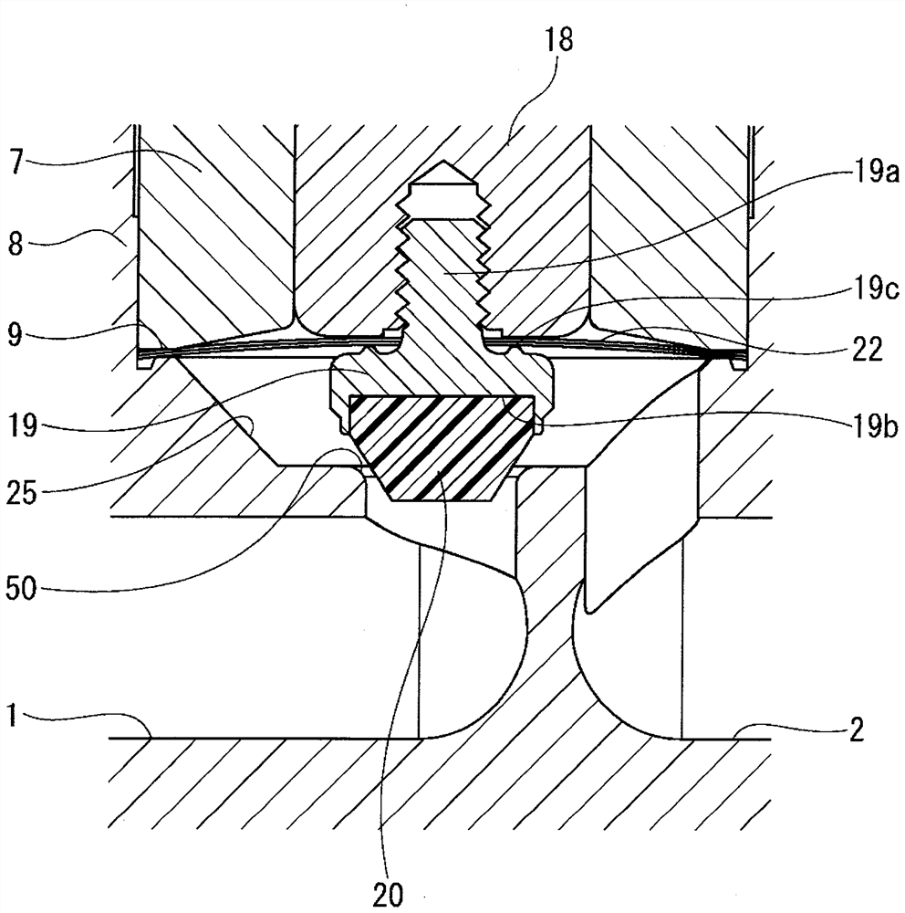
[0044] Hereinafter, the structure of one embodiment (this example) of the present invention will be described in detail based on the drawings. figure 1 It is a longitudinal sectional view showing the fully open state of the diaphragm valve of this example, and first, the overall structure of the valve will be described. In addition, the valve of this figure uses the 2nd sheet|seat 30 as mentioned later.

[0045] exist figure 1 Among them, the main body 3 (valve box) is formed of an integral metal member, and the primary side flow path 1 and the secondary side flow path 2 are linearly pierced. The primary side flow path 1 faces the valve chamber provided in the valve box. 25 communicates through the primary side opening edge, and the secondary side flow path 2 opens in this valve chamber 25 . In the upper part of the valve chamber 25, the cylindrical part 8 is provided, and the outer peripheral surface of this cylindrical part 8 is provided with the male thread part 8a.

[0...


PUM


Abstract

The present invention addresses the problem of providing a diaphragm valve which has a simple configuration, effectively prevents the generation and accumulation of reaction products in a valve body seal part, suppresses occlusion during valve closing, and thus can satisfactorily maintain the isolation properties of the valve even after multiple times of opening and closing and long-term use. Thediaphragm valve has a structure in which a diaphragm piece and a piece holder for holding a conical piece are coupled in a valve housing, the outer peripheral edge of an inner diameter opening of thediaphragm is clamped by the piece holder and the diaphragm piece, the diaphragm piece is held by a bonnet so as to be capable of moving up and down, and the bonnet and the outer peripheral edge of thediaphragm are clamped so that the piece is suspended from the diaphragm. The diaphragm valve is provided with a conical sealing part formed on the conical surface of the piece and a cut-off valve seat part formed on the primary side opening edge of the valve box, reaction products generated on the conical sealing part are cut off through sliding movement of the piece, and the conical sealing partis sealed through the cut-off valve seat part.

Description

technical field [0001] The present invention relates to a diaphragm valve, and more particularly to a diaphragm valve used as an automatic or manual on-off valve in semiconductor manufacturing equipment. Background technique [0002] Generally speaking, the gas piping system in semiconductor manufacturing equipment is composed of a gas supply system for the process chamber and a gas exhaust system. In order to meet the characteristic requirements such as area, the sliding part is small, the dead zone is minimized, and the structure is easy to meet the high gas displacement and cleanability of the diaphragm valve (especially the direct touch type). [0003] Various types of such valves have been proposed, and there are valves shown in Patent Documents 1 to 3, for example. Patent Document 1 is a direct touch type. Its ring-shaped valve seat is fixed on the edge of the opening of the primary side flow path. The diaphragm is clamped on the upper part of the valve seat. When the...

Claims


Application Information

Patent Timeline
Patent Type & Authority Applications(China)
IPC IPC(8): F16K1/38F16K1/42F16K7/12F16K7/14
CPCF16K1/38F16K1/42F16K7/126F16K7/14F16K7/12F16K21/04F16K31/145H01L21/67017
Inventor 高朝克图
Owner 株式会社开滋SCT
Why Eureka
Try Eureka