Machining die, machining device and method for lined wear-resisting layer of iron three-way pipe fitting

A technology for processing molds and wear-resistant layers, which is applied in the direction of pipeline damage/abrasion prevention, pipeline protection, and branch pipelines. The processing workload, the processing process is simple, and the effect of reducing welding requirements

Active Publication Date: 2020-10-09
SHANDONG DONGHONG PIPE IND
View PDF9 Cites 0 Cited by
  • Summary
  • Abstract
  • Description
  • Claims
  • Application Information

AI Technical Summary

Problems solved by technology

However, the inventor found that in the process of conveying the slurry, the galvanized layer or the plastic-coated layer has poor wear resistance and is easy to fall off, causing the steel to be directly exposed to the medium. Due to corrosion and wear, the iron welding tee is accelerated. Rapid damage to pipe fittings
[0005] 2. Ordinary injection molding tee, because the material is made of PE and other materials, because of its low material strength, it can withstand higher pressure by thickening the pipe fittings, but it cannot meet the wear resistance
The iron tee of the lined PE wear-resistant pipe was completed, but the inventor found that the internal PE pipe was easily damaged by welding, resulting in complicated processing and high cost, and the PE pipe was not fully combined with the iron welded tee, and the axial resistance pull ability is weak

Method used


Image

  • Machining die, machining device and method for lined wear-resisting layer of iron three-way pipe fitting
  • Machining die, machining device and method for lined wear-resisting layer of iron three-way pipe fitting
  • Machining die, machining device and method for lined wear-resisting layer of iron three-way pipe fitting

Examples


Embodiment 2

[0036] This embodiment provides a processing device for an iron tee liner wear-resistant layer, including an injection molding machine and the iron tee liner wear-resistant layer processing mold described in Embodiment 1, and the injection molding machine provided by the second part The mouth is matched with the injection molding machine, and the injection molding machine can be an existing injection molding machine, and its specific structure will not be described in detail.

Embodiment 3

[0038]This embodiment discloses a method for the processing device of the iron tee lining wear-resistant layer described in embodiment 2:

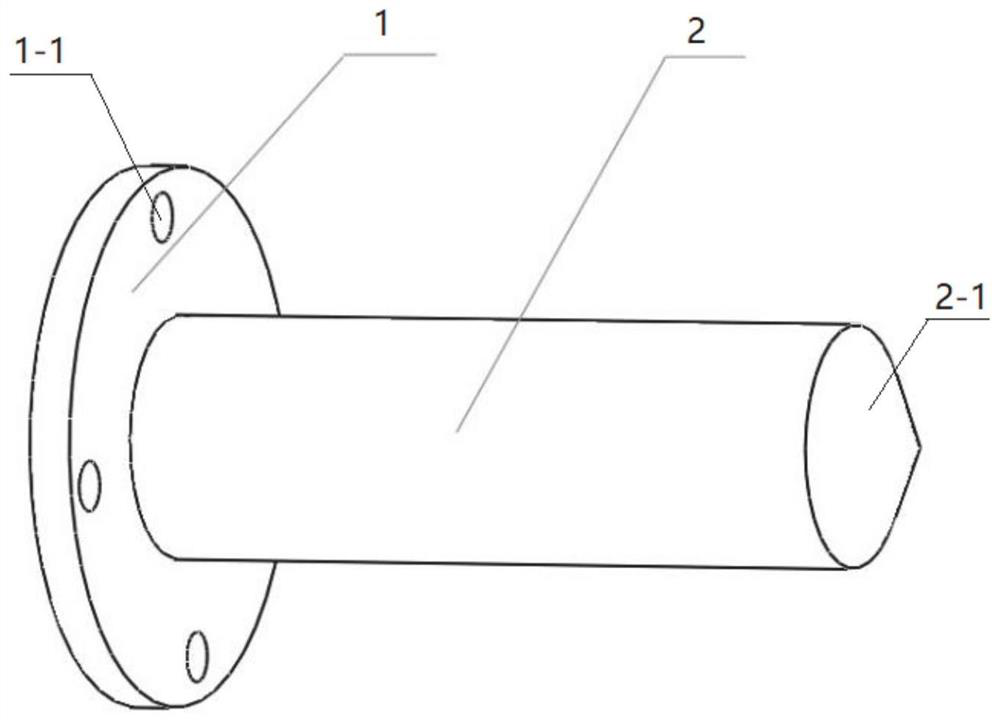
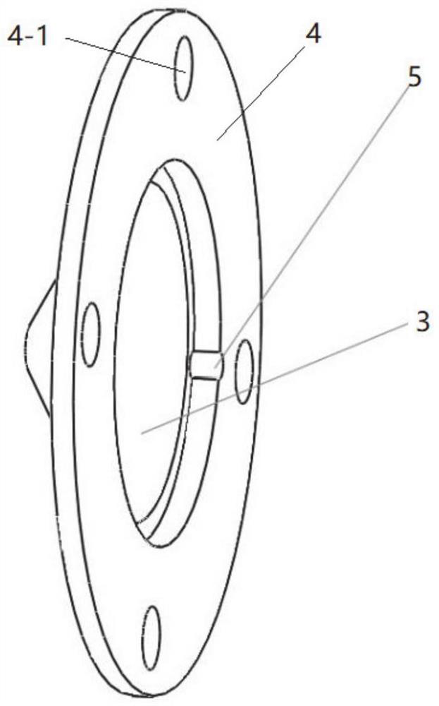
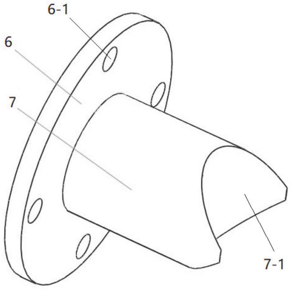
[0039] like Figure 4-5 As shown, the first blind flange of the first part and the connecting flange of the second part are fixed to the first flange 9 and the second flange 10 at both ends of the main pipe 8 of the iron tee through fixing bolts connection, the first mandrel end surface and the inner surface of the injection cap have a gap of 2mm, and the second blind flange of the third part is fixedly connected with the third flange 12 of the branch pipe 11 of the iron tee through fixing bolts, The end of the second mandrel closely fits the outer shaft surface of the first mandrel through the semicircular arc surface to complete the installation of the mold. The first mandrel, the second mandrel, the first blind flange, the second The blind flange, the connecting flange and the injection cap together with the inner surface of the iron t...


PUM


Abstract

The invention relates to a machining die, machining device and method for a lined wear-resisting layer of an iron three-way pipe fitting. The machining die comprises a first component, a second component and a third component; the first component can be fixed to one end of a three-way pipe fitting main pipe in a sealed mode and is provided with a first mandrel capable of coaxially stretching intothe three-way pipe fitting main pipe, and the second component can be fixed at the other end of the three-way pipe fitting main pipe in a sealed mode and can keep a set distance from the end surface of the first mandrel; and the third component can be fixed to the end part of a three-way pipe fitting branch pipe in a sealed mode and is provided with a second mandrel capable of coaxially stretchinginto the three-way pipe fitting branch pipe, and the end part of the second mandrel can make close contact with the outer mandrel face of the first mandrel. The die is convenient to machine and simple in structure, and a machined wear-resisting layer is not prone to fall off.

Description

technical field [0001] The invention relates to the technical field of high-pressure slurry conveying equipment, in particular to a processing mold, processing device and method for an iron tee lining wear-resistant layer. Background technique [0002] The statements herein merely provide background information related to the present invention and do not necessarily constitute prior art. [0003] In the field of high-pressure slurry transportation, various forms of pipelines have emerged to solve difficult problems such as high pressure and wear resistance, but in terms of pipe fittings, the problem of combining high pressure and wear resistance has not been able to be solved. The tee can only unilaterally solve the characteristics of high pressure or wear resistance. for example: [0004] 1. Ordinary iron welding tees, the common anti-corrosion methods are galvanized or plastic-coated, processed with steel, and the pipe body has high strength. When transporting pure liqu...

Claims


Application Information

Patent Timeline
Patent Type & Authority Applications(China)
IPC IPC(8): F16L41/02F16L57/06B29C45/14
CPCF16L41/021F16L57/06B29C45/14
Inventor 倪奉尧戚书刚孔智勇韩夫娥徐将
Owner SHANDONG DONGHONG PIPE IND
Why Eureka
Try Eureka