
Quick plugging and dissociation device and method for liquefied natural gas small hole high-pressure leakage

A technology of liquefied natural gas and high pressure, which is applied in the direction of container filling method, container discharge method, container structure installation device, etc., which can solve the problems of liquefied natural gas storage tank leakage and inability to be effectively fixed, and achieve the effect of avoiding explosion accidents

Pending Publication Date: 2020-10-09
UNIV OF SCI & TECH OF CHINA
View PDF2 Cites 1 Cited by
  • Summary
  • Abstract
  • Description
  • Claims
  • Application Information

AI Technical Summary

Problems solved by technology

However, the size of the LNG storage tank is larger than that of the pipeline. The radius of the common horizontal storage tank is 2m to 3m, and the length is 13m to 18m; the radius of the common spherical tank is 3m to 5m, so the size of the leak of the LNG storage tank is relatively large. Because the pipeline is much larger, especially the convex spherical surface at both ends of the horizontal tank and the wall of the spherical tank have a large radius of curvature, so the traditional sealing device for pipeline leakage cannot be effectively fixed when the LNG storage tank leaks.

Method used


Image

  • Quick plugging and dissociation device and method for liquefied natural gas small hole high-pressure leakage
  • Quick plugging and dissociation device and method for liquefied natural gas small hole high-pressure leakage
  • Quick plugging and dissociation device and method for liquefied natural gas small hole high-pressure leakage

Examples


Embodiment Construction

[0028] In order to make the purpose, implementation and technical advantages of the present invention clearer, the technical solutions during the implementation of the present invention will be clearly and completely described in conjunction with the accompanying drawings in the present invention. It is claimed here that the described implementation examples are some, but not all, embodiments of the invention. Based on the embodiments of the present invention, all other embodiments obtained by persons of ordinary skill in the art without making creative efforts belong to the scope of protection of the present invention.

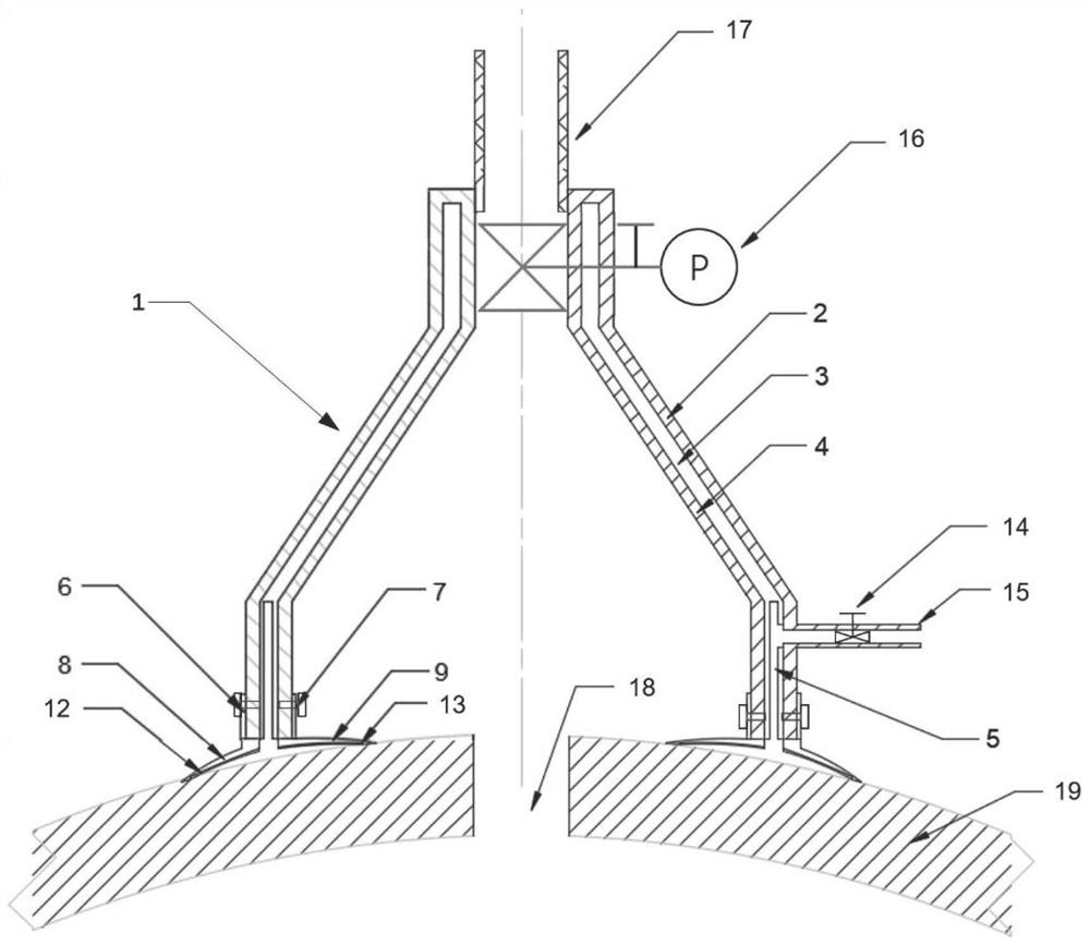
[0029] Such as figure 1 As shown, this embodiment is a rapid plugging and extraction device for small hole high-pressure leakage of liquefied natural gas. The main body 1 of the device is composed of an outer shell 2, a middle heat insulation layer 3 and an inner cold-resistant layer 4. One end of the middle heat insulation layer 3 contains Vacuum chamber 5. ...


PUM


Abstract

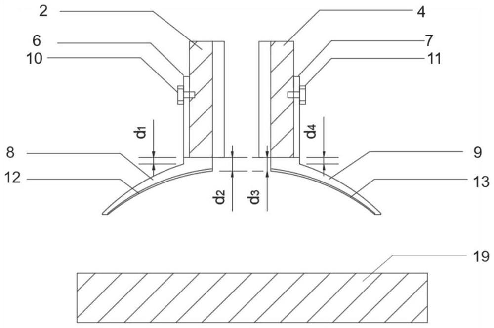
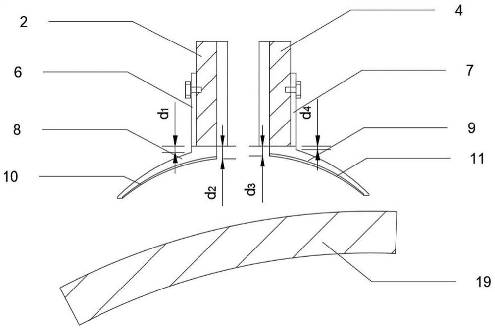
The invention discloses a quick plugging and dissociation device and method for liquefied natural gas small hole high-pressure leakage. The device comprises a device main body which is composed of a housing, a middle thermal insulation layer and an internal cold-resistant layer, and the device main body is in an inverted funnel shape; one end of the middle heat insulation layer is wrapped with anopen cavity to form a vacuum cavity, the housing is fixed to an outer sucker through an outer sucker clamp and an outer bolt, and the inner cold-resistant layer is fixed to an inner sucker through aninner sucker clamp and an inner bolt; the vacuum cavity is connected with a vacuum air exhaust interface and is externally connected with a vacuum air pump; and one end of the device main body is provided with an external extraction connector connected with an external compressor. Leaked substances can be rapidly plugged under the condition that a fire source exists outside, fire enhancement caused by continuous leakage and explosion caused by pressure increase in the tank body are avoided, the characteristic that the pressure in the device main body is increased due to the leaked substances is fully utilized to enable the inner sucker to provide adsorption force, the better sealing performance is achieved, and the device has the advantages of quick installation and simple operation.

Description

technical field [0001] The invention relates to a leakage prevention device for fast blocking, in particular to a device and method for rapid blocking and extraction of small hole high-pressure leakage of liquefied natural gas. Background technique [0002] As a clean and efficient energy source, natural gas is widely used by people. The liquefaction of natural gas to form liquefied natural gas can compress the volume of natural gas by nearly 620 times, which greatly improves the efficiency of natural gas transportation and storage. However, due to accidents or the influence of the natural environment, leakage of liquefied natural gas may occur, causing fire or explosion. [0003] The liquefaction temperature of liquefied natural gas under normal pressure is -162°C, and it is generally stored under normal pressure within the pressure range of 0.3Mpa to 0.8Mpa. In order to save storage costs, the wall of the container is generally a sandwich structure, that is, the inner la...

Claims


Application Information

Patent Timeline
Patent Type & Authority Applications(China)
IPC IPC(8): F17C13/00F17C13/04F17C13/12F16L59/02F16L59/065
CPCF16L59/029F16L59/065F17C13/00F17C13/04F17C13/12F17C2203/03F17C2205/0302F17C2221/033F17C2227/0157F17C2260/037F17C2260/042
Inventor 谢启源卢启钊袁焱华
Owner UNIV OF SCI & TECH OF CHINA
Learn More