Rock crack observation device and method
A technology of rock fractures and observation devices, applied in the directions of measuring devices, analysis of suspensions and porous materials, fluorescence/phosphorescence, etc.
- Summary
- Abstract
- Description
- Claims
- Application Information
AI Technical Summary
Problems solved by technology
Method used
Image
Examples
Embodiment 1
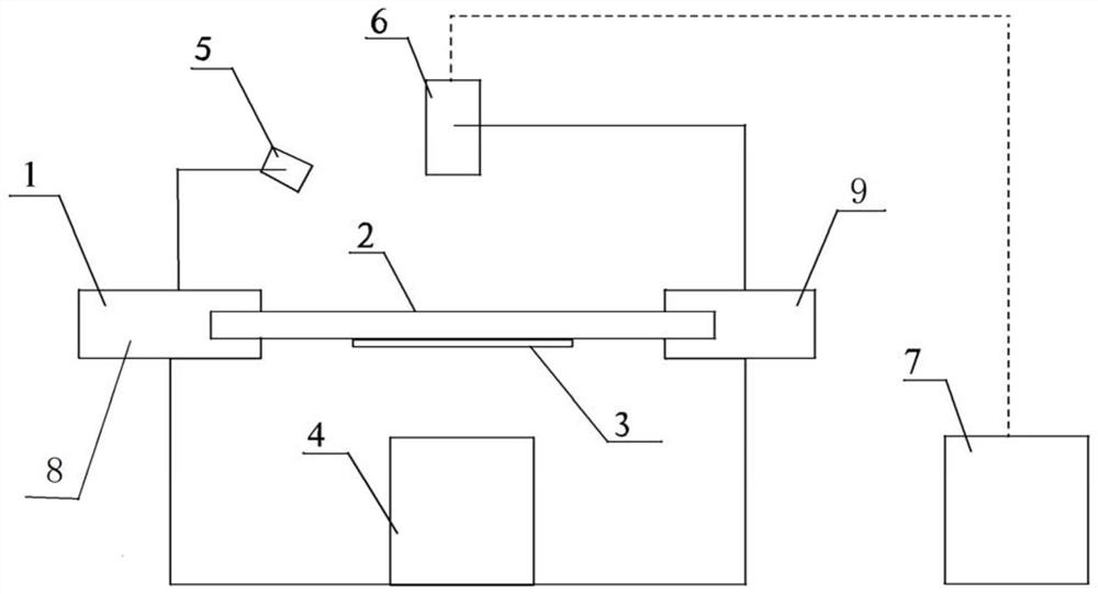
[0061] figure 1 A schematic structural diagram of a rock fracture observation device in an embodiment of the present invention is shown. Such as figure 1 As shown, the embodiment provides a rock fracture observation device, comprising:
[0062] The stage 1, the stage 1 is used to fix the rock sample 2; the magnetic field generator 4, the magnetic field generator 4 is used to apply magnetic force to the rock sample 2; the light source 5, the light source 5 is used to irradiate the rock sample 2 so that The surface of the fluorescent image is formed; the imaging device 6 is used for collecting the fluorescent image.
[0063] The stage 1 fixes the rock sample 2 along the horizontal direction; the magnetic field generator 4 is arranged under the stage 1 for generating magnetic force in the vertical direction; the light source 5 is arranged above the stage 1 for illuminating the rock sample 2 Upper surface: The imaging device 6 is arranged above the stage 1 and is used to collec...
Embodiment 2
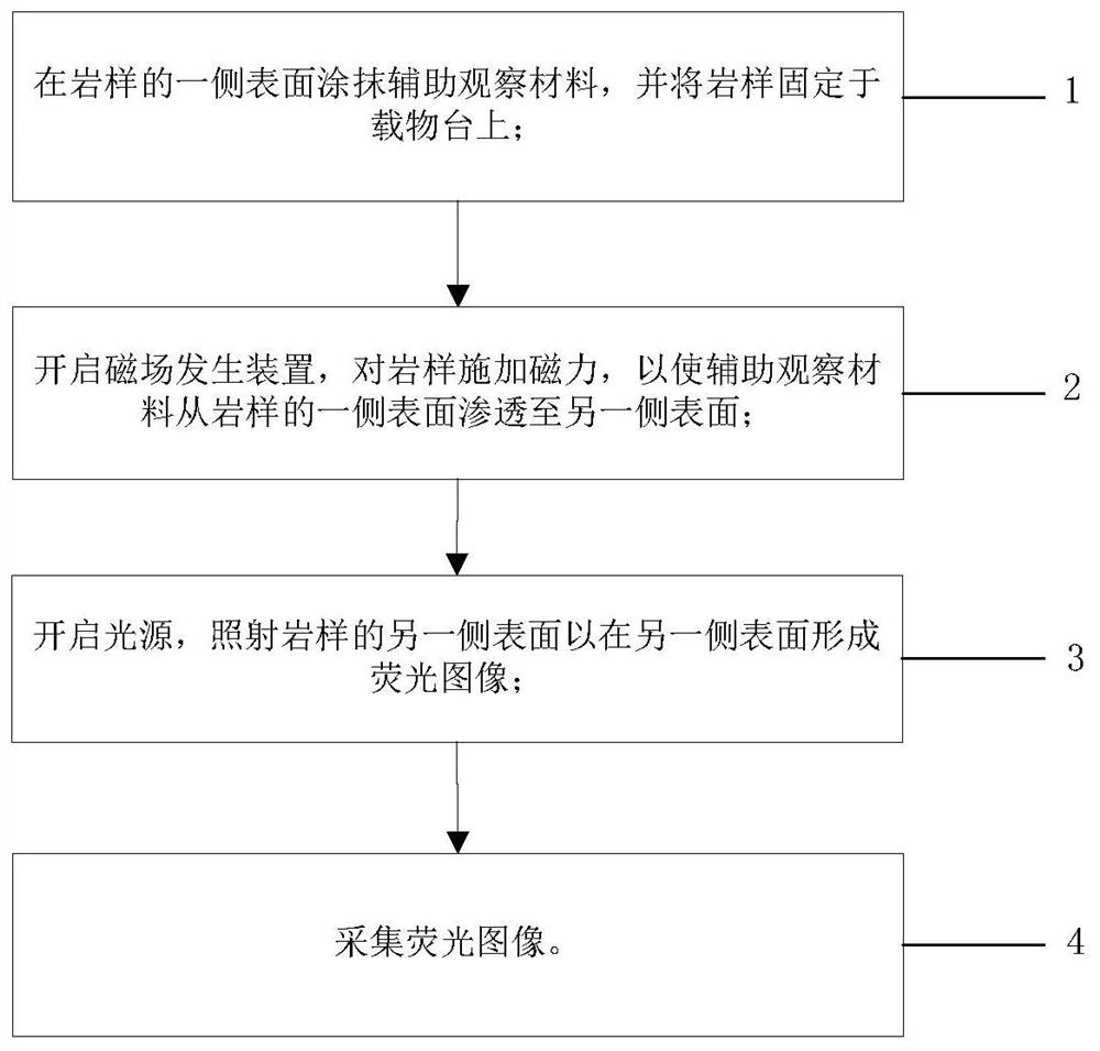
[0066] figure 2 A flow chart of the method for observing rock fractures in one embodiment of the present invention is shown.
[0067] Such as figure 2 As shown, the embodiment provides a rock fracture observation method, the method includes the following steps:
[0068] Step 1: The stage 1 includes a first clamping portion 8 and a second clamping portion 9 which are arranged oppositely, grooves are provided on the inner surface of the first clamping portion 8 and the inner surface of the second clamping portion 9, The groove is used to hold the rock sample 2. The rock sample 2 is processed into sheets, and the thickness of the rock sample 2 is smaller than the height of the groove.
[0069] Step 2: Apply auxiliary observation material 3 on one side of the rock sample 2, and fix the rock sample 2 on the stage 1.
[0070] The stage 1 fixes the rock sample 2 along the horizontal direction, the magnetic field generating device 4 is arranged under the stage 1, the light sourc...
PUM
 Abstract
Description
Claims
Application Information
 - R&D
- Intellectual Property
- Life Sciences
- Materials
- Tech Scout
- Unparalleled Data Quality
- Higher Quality Content
- 60% Fewer Hallucinations
Browse by: Latest US Patents, China's latest patents, Technical Efficacy Thesaurus, Application Domain, Technology Topic, Popular Technical Reports.
© 2025 PatSnap. All rights reserved.Legal|Privacy policy|Modern Slavery Act Transparency Statement|Sitemap|About US| Contact US: help@patsnap.com


