
Rotating speed real-time test system based on data acquisition and control method

A data acquisition system, real-time testing technology, applied in devices using electrical/magnetic methods, program control, computer control, etc., can solve problems such as inability to meet test requirements, and achieve high speed or frequency testing and control accuracy, line Easy connection, guaranteed accuracy

Pending Publication Date: 2020-10-09
内蒙航天动力机械测试所
View PDF8 Cites 0 Cited by
  • Summary
  • Abstract
  • Description
  • Claims
  • Application Information

AI Technical Summary

Problems solved by technology

At present, real-time testing and judgment cannot be realized for the frequency test of the speed sensor. Only the original pulse data output by the sensor can be tested, and the output frequency of the speed sensor can be determined by post-test processing. In addition, the condition interpretation of the data acquisition system is limited to judging one signal and Only a single corresponding feedback signal is output, and the simultaneous judgment of two signals in the task has not been realized, so the existing frequency test method cannot meet the test requirements of the test in the background technology

Method used


Image

  • Rotating speed real-time test system based on data acquisition and control method
  • Rotating speed real-time test system based on data acquisition and control method
  • Rotating speed real-time test system based on data acquisition and control method

Examples


Embodiment Construction

[0039] The present invention will be further described below in conjunction with the accompanying drawings and specific embodiments of the propellant electromagnetic radiation sensitivity testing device and method.

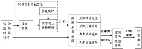
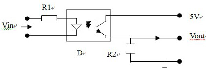
[0040] Such as figure 1 As shown, a real-time speed test system based on data acquisition includes a real-time speed test unit, a data acquisition system, a control signal processing module, and a control center; the real-time speed test unit includes an isolation module, a power supply module, and a frequency-voltage conversion module. The isolation module is used to isolate interference, and the power supply module provides working voltage for the frequency voltage conversion module, and the frequency voltage conversion module is used to convert the speed or frequency signal from the test site into a voltage value of 0-5V in real time; The data acquisition system judges the rotational speed voltage and the pressure signal by collecting the rotational speed volta...


PUM


Abstract

The invention relates to the field of test equipment and intelligent monitoring, in particular to a rotating speed real-time test system based on data acquisition and a control method. The system comprises a rotating speed real-time test unit, a data acquisition system, a control signal processing module and a control center. The rotating speed real-time test unit comprises an isolation module, apower supply module and a frequency voltage conversion module, the data acquisition system judges a rotating speed voltage and a pressure signal by acquiring the rotating speed voltage and the pressure signal, and the control signal processing module is used for processing a control signal generated by the data acquisition system; and the control center is used for testing and monitoring the rotating speed in time according to the signal generated by the control signal processing module. Real-time testing of the output pulse frequency of the rotating speed sensor can be realized, rapid interpretation is performed according to the frequency and the pressure, and a feedback signal is sent to the control center so that the reliability and the accuracy of real-time testing and control of the test can be enhanced, the test measurement and control level can be enhanced and the test measurement and control range can be expanded.

Description

technical field [0001] The invention relates to the field of testing equipment and intelligent monitoring, in particular to a real-time testing system and control method for a rotational speed based on data collection. Background technique [0002] In a specific test, it is required to monitor the output frequency of the servo mechanism oil pump speed sensor and the output signal of the oil pump outlet pressure sensor in real time, and make a real-time judgment based on the real-time test data 2 seconds before the test. Only when the judgment conditions indicate that the servo mechanism is working normally can a feedback signal be sent to the control center, and the control center can continue to test only after receiving the feedback signal. Therefore, the test and judgment of the output frequency of the pump speed sensor and the output signal of the oil pump outlet pressure sensor are very important and the key to the success of the test. At present, real-time testing and...

Claims


Application Information

Patent Timeline
Patent Type & Authority Applications(China)
IPC IPC(8): G01P3/46G05B19/042
CPCG01P3/46G05B19/0423
Inventor 陈丽霞蒋韫韬
Owner 内蒙航天动力机械测试所
Learn More