Airborne laser point cloud overlapping degree detection method and system

An airborne laser and detection method technology, applied in the field of image processing, can solve the problems of affecting data usage, small field of view, poor reliability and scientificity, etc., to achieve the effect of automation, improve efficiency and reliability

Pending Publication Date: 2020-10-09
SICHUAN SURVEYING & MAPPING PROD QUALITY SUPERVISION & INSPECTION STATION OF THE MINIST OF NATURAL RESOURCES SICHUAN SURVEYING & MAPPING PROD QUALITY SUPERVISION & INSPECTION STATION
View PDF0 Cites 0 Cited by
  • Summary
  • Abstract
  • Description
  • Claims
  • Application Information

AI Technical Summary

Problems solved by technology

However, the airborne lidar equipment has a small field of view and a low flight height. It is greatly affected by factors such as terrain fluctuations, wind force, and mirror reflections of ground objects during aerial photography. Areas that do not meet the overlapping degree are prone to appear, which directly affects the quality of the data. use
However, the human-computer interaction and point cloud overlap detection methods that are often used at intervals along the flight direction are low in efficiency, poor in reliability and scientificity, and cannot effectively control the cost of aerial photography and the quality of point cloud data.

Method used


Image

  • Airborne laser point cloud overlapping degree detection method and system
  • Airborne laser point cloud overlapping degree detection method and system
  • Airborne laser point cloud overlapping degree detection method and system

Examples


Embodiment Construction

[0064] The following will clearly and completely describe the technical solutions in the embodiments of the present invention with reference to the accompanying drawings in the embodiments of the present invention. Obviously, the described embodiments are only some, not all, embodiments of the present invention. Based on the embodiments of the present invention, all other embodiments obtained by persons of ordinary skill in the art without making creative efforts belong to the protection scope of the present invention.

[0065] In order to make the above objects, features and advantages of the present invention more comprehensible, the present invention will be further described in detail below in conjunction with the accompanying drawings and specific embodiments.

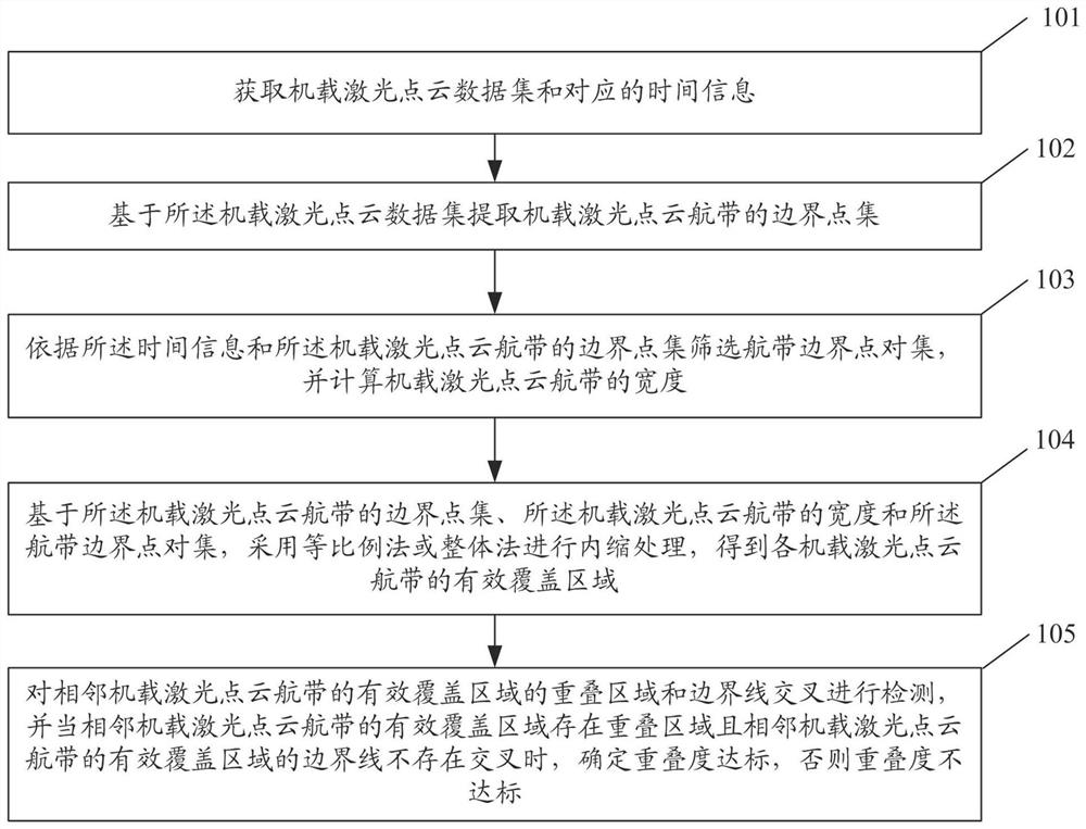
[0066] figure 1 It is a flowchart of an airborne laser point cloud overlap detection method provided by an embodiment of the present invention.

[0067] see figure 1 , the airborne laser point cloud overlap dete...


PUM


Abstract

The invention discloses an airborne laser point cloud overlapping degree detection method and system. The airborne laser point cloud overlapping degree detection method comprises the steps: extractinga boundary point set of an airborne laser point cloud air strip based on an airborne laser point cloud data set; calculating the width of the onboard laser point cloud air strip; on the basis of theboundary point set of the airborne laser point cloud air strip, the width of the airborne laser point cloud air strip and the air strip boundary point pair set, using an equal proportion method or anintegral method to carry out inward shrinkage processing to obtain an effective coverage area of each airborne laser point cloud air strip; and detecting the intersection of the overlapping area and the boundary line of the effective coverage areas of the adjacent airborne laser point cloud air strips, and when the overlapping area exists in the effective coverage area of the adjacent airborne laser point cloud air strip and the boundary lines do not intersect, determining that the overlapping degree reaches the standard, otherwise, determining that the overlapping degree does not reach the standard. According to the invention, the overlapping degree detection efficiency and reliability can be improved.

Description

technical field [0001] The invention relates to the field of image processing, in particular to an airborne laser point cloud overlapping degree detection method and system. Background technique [0002] Airborne lidar technology has been widely used in the production of digital surface model (DSM), digital elevation model (DEM) and digital ortho imagery (DOM). However, the airborne lidar equipment has a small field of view and a low flight height. It is greatly affected by factors such as terrain fluctuations, wind force, and mirror reflections of ground objects during aerial photography. Areas that do not meet the overlapping degree are prone to appear, which directly affects the quality of the data. use. However, the human-computer interaction and point cloud overlap detection methods that are often used at intervals along the flight direction are low in efficiency, poor in reliability and scientificity, and cannot effectively control the cost of aerial photography and t...

Claims


Application Information

Patent Timeline
IPC IPC(8): G06T7/13G06T7/00G01S17/89G01S7/497G01C11/04
CPCG01C11/04G01S7/497G01S17/89G06T7/0002G06T7/13
Inventor 李昊霖陈琰如佘毅
Owner SICHUAN SURVEYING & MAPPING PROD QUALITY SUPERVISION & INSPECTION STATION OF THE MINIST OF NATURAL RESOURCES SICHUAN SURVEYING & MAPPING PROD QUALITY SUPERVISION & INSPECTION STATION
Why Eureka
Try Eureka