Multi-phase multi-duty-ratio clock generation circuit

A technology of clock generation circuit and duty cycle, applied in the direction of electric pulse generation, multiple input and output pulse circuits, pulse generation, etc., can solve the problem of single duty cycle output state, limited operating frequency range, low maximum operating frequency, etc. problem, achieve the effect of overcoming poor frequency characteristics, good common mode noise suppression ability, and good matching characteristics

Active Publication Date: 2020-10-09
INST OF MICROELECTRONICS CHINESE ACAD OF SCI
View PDF6 Cites 0 Cited by
  • Summary
  • Abstract
  • Description
  • Claims
  • Application Information

AI Technical Summary

Problems solved by technology

The disadvantage is that the operating frequency range is still limited, the bandwidth is still narrow, and the duty cycle is single
In the patent document "A 25% Duty Cycle Clock Signal Generation Circuit" (Application No. CN201610622753.5, Publication No. CN106257835A), Wu Jianhui et al. of Southeast University also disclosed a 25% duty ratio built by CMOS. The four-phase clock generation circuit uses the phase difference of the frequency divider signal to generate a four-phase clock. The advantage is that the principle is simple and the power consumption is low. The disadvantage is still that the CMOS device is used, the clock bandwidth is limited, the maximum operating frequency is low and the duty cycle is low. single than the output state

Method used


Image

  • Multi-phase multi-duty-ratio clock generation circuit
  • Multi-phase multi-duty-ratio clock generation circuit
  • Multi-phase multi-duty-ratio clock generation circuit

Examples


Embodiment 1

[0049] The embodiment of the present disclosure provides a multi-phase multi-duty cycle clock generation circuit, which will be combined with the following figure 1 - attached Image 6 , a multi-phase multi-duty cycle clock generation circuit provided in the embodiment of the present application is introduced in detail.

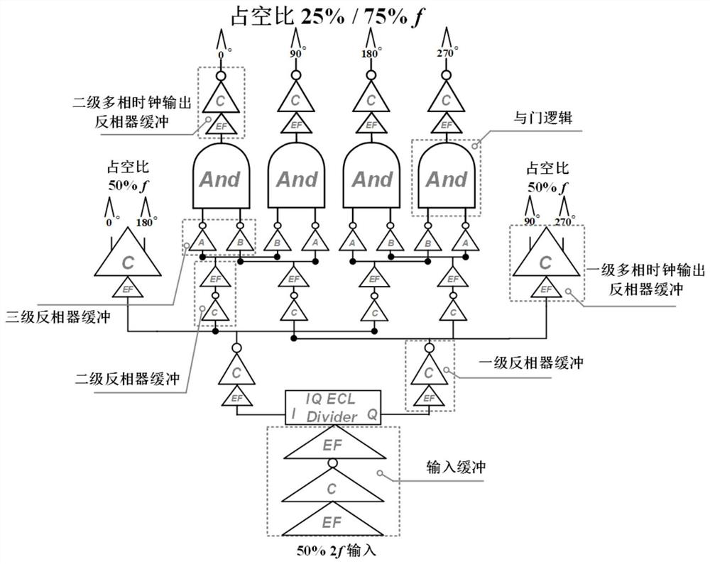
[0050] figure 1 It is a structural schematic diagram of a multi-phase multi-duty cycle clock generation circuit shown according to an exemplary embodiment. like figure 1 As shown, a multi-phase multi-duty cycle clock generation circuit, including:

[0051] Input buffer module, its input terminal receives the input signal, and the output terminal is connected to the input terminal of the frequency divider; in some exemplary scenarios, input a clock signal with a duty ratio of 50%, after being buffered and amplified by the input buffer module, the above signal is sent to the input of the divider.

[0052] Specifically, the input buffer module is composed o...

Embodiment 2

[0073] The embodiment of the present disclosure provides a simulation example of a multi-phase multi-duty cycle clock generation circuit.

[0074] Figure 7 It is a schematic diagram of simulation results of a multi-phase multi-duty cycle clock generation circuit shown according to an exemplary embodiment.

[0075] In a possible implementation manner, a 0.8 μm InP DHBT device process library is used to simulate the characteristics of the multi-phase clock generation circuit of the embodiment of the present disclosure in ADS software.

[0076] Specifically, the circuit characteristics include the frequency range of the clock applied at the input, including the highest frequency and the lowest frequency, and the highest output spectrum of clocks with different duty ratios. The output waveforms corresponding to the frequencies respectively.

[0077] Figure 7 (a) is the multi-phase clock generation circuit of the embodiment of the present disclosure input 93GHz, output 46.5GHz...


PUM


Abstract

The invention discloses a multi-phase multi-duty-ratio clock generation circuit, which comprises an input buffer module of which the input end receives an input signal and the output end is connectedwith the input end of a frequency divider; the frequency divider of which the output end is connected with the input ends of two primary inverters; the two primary inverters, wherein the output end ofthe first primary inverter is connected with the input ends of a first secondary inverter and a third secondary inverter and the input end of a first primary clock output inverter, and the output endof the second first primary inverter is connected with the input ends of a second secondary inverter and a fourth secondary inverter and the input end of the second primary clock output inverter; thefour secondary intervers, wherein the output end of each secondary inverter is connected with the input ends of the two tertiary inverters; eight tertiary inverters connected with four AND gates; andthe four AND gates, wherein the output ends of the eight tertiaryinverters are connected with the first to fourth secondary clock output inverters respectively; and four secondary clock output inverters. The circuit overcomes the defects of low signal frequency, narrow bandwidth and single duty ratio of a multi-phase clock generation circuit.

Description

technical field [0001] The invention relates to the technical field of integrated circuits, in particular to a clock generation circuit with multiple phases and multiple duty ratios. Background technique [0002] At present, the multi-phase clock generation circuit can use the fixed-phase clock signal to generate multiple frequency-divided signals with fixed phase difference and fixed duty cycle or their frequency-multiplied signals, which are often used as the front end of the interleaving circuit. The requirements are getting higher and higher, and the clock interleaving technology is an important way to improve the working speed of the circuit, so the generation of multi-phase clocks is particularly important. [0003] In the prior art, almost all multi-phase clock generation circuits are built using CMOS (Complementary Metal Oxide Semiconductor, Complementary Metal Oxide Semiconductor) devices, which generally can only generate clock signals with a constant duty cycle, a...

Claims


Application Information

Patent Timeline
Patent Type & Authority Applications(China)
IPC IPC(8): H03K3/017H03K5/22
CPCH03K3/017H03K5/22
Inventor 甄文祥苏永波李少军金智
Owner INST OF MICROELECTRONICS CHINESE ACAD OF SCI
Why Eureka
Try Eureka