Auxiliary device for automatically cutting long round hole on site

An automatic cutting and auxiliary device technology, applied in auxiliary devices, welding/cutting auxiliary equipment, auxiliary welding equipment, etc., can solve the problems of unguaranteed construction period and quality, failure to meet quality requirements, high labor and time costs, and save grinding Process and time costs, reduction of operator skill requirements, and the effect of reducing skill requirements

Active Publication Date: 2020-10-13
SINOPEC NINGBO ENG +2
View PDF5 Cites 0 Cited by
  • Summary
  • Abstract
  • Description
  • Claims
  • Application Information

AI Technical Summary

Problems solved by technology

The above schemes have high requirements on the personal skills of cutting personnel, the actual processing quality often cannot meet the quality requirements, and the workload of grinding after cutting is large, especially when there are many holes to be cut, the construction period and quality cannot be guaranteed, and the labor and time costs are high.

Method used


Image

  • Auxiliary device for automatically cutting long round hole on site
  • Auxiliary device for automatically cutting long round hole on site
  • Auxiliary device for automatically cutting long round hole on site

Examples


Embodiment 1

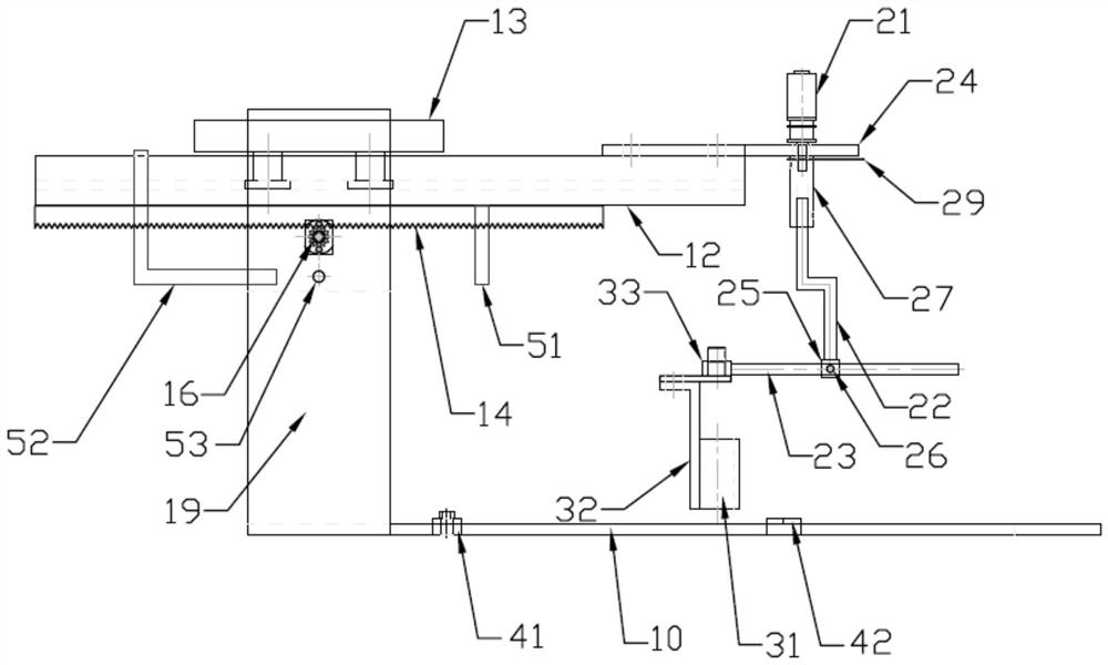
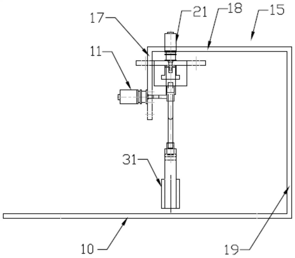
[0022] The on-the-spot strip round hole automatic cutting auxiliary device of embodiment 1, as Figure 1-Figure 3 As shown, it includes a linear drive assembly, an arc drive assembly, a cutting nozzle installation assembly for clamping the cutting nozzle (not shown in the figure), an electrical control box (not shown in the figure), an arc drive assembly and a linear drive The components are connected, the linear drive component is used to drive the arc drive component for linear motion, the cutting nozzle installation component is connected with the arc drive component, and the arc drive component is used to drive the cutting nozzle installation component with the cutting nozzle for circular arc movement, The operation of the linear drive assembly and the arc drive assembly is controlled by the electrical control box.

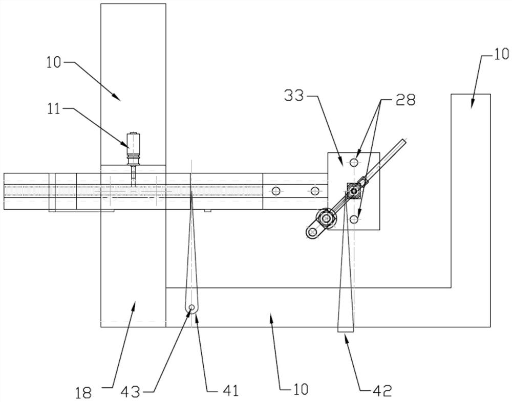
[0023]In Embodiment 1, the linear drive assembly includes a first motor 11, a guide rail 12, a slider 13, a rack 14 and a bracket 15, the rack 14 is fixed on ...

Embodiment 2

[0026] The difference between the on-site automatic cutting auxiliary device for long strips and round holes in embodiment 2 is that in embodiment 2, a zero-position baffle 51 and a moving baffle 52 are arranged on the guide rail 12, and the zero-position baffle 51 is upright and fixed On the front side of the guide rail 12, the movable baffle plate 52 is magnetically adsorbed on the front side of the guide rail 12, the front side of the guide rail 12 is provided with a linear segment cutting length scale line (not shown in the figure), and the rear side plate 17 is equipped with The length control sensor 53 that the mobile baffle 52 is adapted, the length control sensor 53 is electrically connected with the electric control box, and the mobile baffle 52 and the zero position baffle 51 are used to adjust the length of the elongated circular hole to be cut on the workpiece to be processed. Straight line section cutting length; two positioning sensors 28 are installed front and r...


PUM


Abstract

The invention discloses an auxiliary device for automatically cutting a long round hole on site. The auxiliary device for automatically cutting the long round hole on site includes a linear drive assembly, an arc drive assembly, a cutting nozzle mounting assembly for clamping a cutting nozzle, and an electric control box; the arc drive assembly is connected to the linear drive assembly, and the linear drive assembly is used for driving the arc drive assembly to perform linear motion; the cutting nozzle mounting assembly is connected to the arc drive assembly, and the arc drive assembly is usedfor driving the cutting nozzle mounting assembly mounted with the cutting nozzle to perform circular motion; and the operation of the linear drive assembly and the arc drive assembly is controlled byan electric control box. The auxiliary device for automatically cutting the long round hole on site is flexible and convenient to use, meets the operation needs of the three-dimensional space on theproduction site, achieves the improvement of processing efficiency and lowering the skill requirements of operators, guarantees the cutting quality of the long round holes on plates of different thicknesses, makes the cutting surface smoother, and only needs simple grinding after cutting to meet the quality specification requirements, which improves the production efficiency and saves the polishing process and time cost.

Description

technical field [0001] The invention relates to the field of welding and cutting, in particular to an auxiliary device for automatically cutting long strips and round holes on site to assist automatic flame or automatic plasma cutting equipment. Background technique [0002] In petrochemical installations, the bolt fixing holes of towers, containers, column bases and the bolt connection holes that need to have adjustment functions in the connecting structural parts need to be processed into long strip bolt fixing holes (that is, long round holes) with a certain length. , to facilitate the installation of bolts. In factory processing, you can rely on CNC cutting machines, profiling cutting machines, etc. to cut and process long strips of round holes, but for the opening of long and heavy profiles, the opening of on-site climbing maintenance construction, etc. Due to construction conditions and other reasons, the cutting machine cannot meet the requirements of hole opening pr...

Claims


Application Information

Patent Timeline
IPC IPC(8): B23K37/02B23K7/10B23K10/00
CPCB23K37/0252B23K7/105B23K10/00
Inventor 洪旭东陆方军封海峰沈祝扬盛光磊
Owner SINOPEC NINGBO ENG
Why Eureka
Try Eureka