Drop energy dissipating structure for ultra-deep inspection well

An inspection well and ultra-deep technology, applied in drainage structures, waterway systems, water supply devices, etc., can solve the problems of ultra-deep inspection wells without specially designed maintenance channels, difficulty in maintenance and maintenance, and unfavorable gas circulation in the well.

Pending Publication Date: 2020-10-13
中铁四川生态城投资有限公司
View PDF1 Cites 2 Cited by
  • Summary
  • Abstract
  • Description
  • Claims
  • Application Information

AI Technical Summary

Problems solved by technology

[0002] At present, the method of dropping water wells is mostly designed as a conventional type of falling water plate energy dissipation. This method has better energy dissipation effect and simple construction, but it is not conducive to the gas circulation in the well, and there is no special design and maintenance for ultra-deep inspection wells. Passage, difficult maintenance in later maintenance, easy to cause safety hazards in later maintenance and repair

Method used


Image

  • Drop energy dissipating structure for ultra-deep inspection well
  • Drop energy dissipating structure for ultra-deep inspection well
  • Drop energy dissipating structure for ultra-deep inspection well

Examples


Embodiment 1

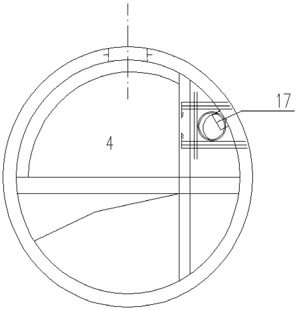
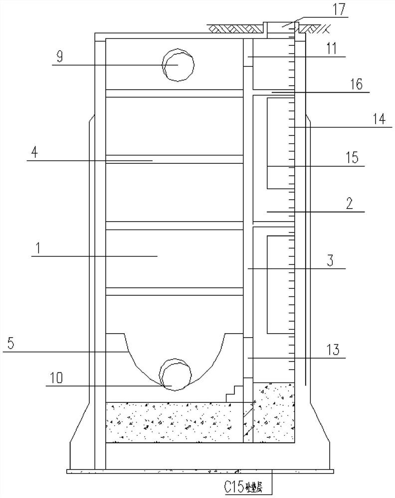
[0040] Such as Figure 1-3 As shown, this embodiment provides a water drop energy dissipation structure applied to ultra-deep inspection wells, including a drainage channel and an inspection channel. On the partition wall, the drainage channel and the maintenance channel are divided into two areas, which is convenient for the staff to do maintenance work on the ultra-deep inspection well;

[0041] A drop plate is arranged in the drainage channel, and a flow channel is arranged under the drop plate at the bottom of the drainage channel, and the flow channel is arranged in an arc shape to introduce sewage into the water outlet pipe;

[0042] The falling boards are arranged staggeredly from top to bottom and on the inside of the left and right walls. Preferably, the vertical distance between the falling boards is 2450mm, and the energy dissipation effect of the selected distance height difference is adopted; The outer side of the drop board is connected to the baffle through the...

Embodiment 2

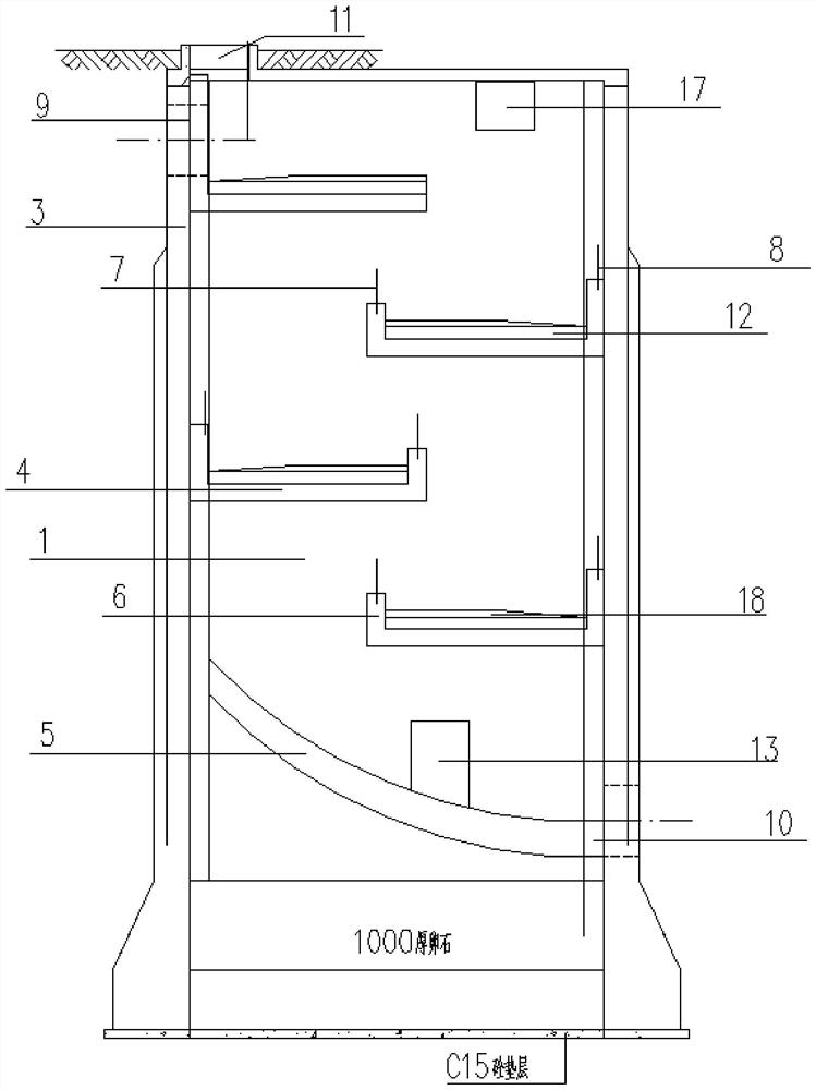
[0050] Such as image 3 As shown, this embodiment provides a water drop energy dissipation structure applied to ultra-deep inspection wells, including a water drop plate and a baffle connected to the water drop plate, and the water drop plate and the baffle cooperate to realize energy dissipation and reduce noise effect;

[0051] In this embodiment, preferably, the height difference between the first drop board on the upper part and the sewage inlet pipe is less than 1000mm, and due to the small height difference, no baffle is provided on the first drop board; preferably, the surface of a drop board is laid A 200mm thick C20 concrete energy dissipation layer, and a 200mm thick pebble energy dissipation layer laid on the lower dropboard;

[0052] According to the impulse formula F t =△E p ,E p = mv; so F t =△E p =mv-mv 0 =m(v-v 0 ), draw F={m(v-v 0 )} / t;

[0053] In the formula, m is the mass of the object, v is the final velocity, and v 0 is the initial velocity, t ...

Embodiment 3

[0058] Such as image 3 As shown, this embodiment provides a water drop energy dissipation structure applied to ultra-deep inspection wells, including a chute added at the bottom, the chute is arc-shaped, and the energy-dissipated sewage is introduced into the outlet pipe;

[0059] According to the parabolic formula x 2 = 2py, the derived slope k = △Y / △X;

[0060] In this embodiment, the arc-shaped trough belongs to a form of parabola. Preferably, the height of the trough is set to 4000mm and the width is 6800mm; according to the formula k=ΔY / ΔX, ΔY=4000, ΔX= 6800, calculated k=0.588, according to the formula tanA=0.588, A=arctan0.588≈180°XK+30.46°;

[0061] Preferably, the launder is arranged at an oblique angle of 30°, and the angle is an optimal scheme for setting the launder to provide initial power for the sewage to enter the pipeline;

[0062] Preferably, a 100mm thick asphalt board is laid on the launder. The asphalt board has good noise reduction and waterproof effe...


PUM


Abstract

The invention discloses a drop energy dissipating structure for an ultra-deep inspection well and relates to the technical field of architectural engineering construction. According to the drop energydissipating structure for the ultra-deep inspection well, a partition plate is designed in a drop well to separate a drainage channel and an maintenance channel, a baffle is additionally arranged toachieve a better energy dissipating effect, and the bottom is provided with a runner to provide initial power for sewage to enter the pipeline. Compared with a traditional structure, the drop energy dissipating structure is convenient to construct, simple, safe and reliable in operation and convenient to operate and maintain in a later period; and holes are reserved on the bottom and the top of the structure to provide air convection channels, drainage is facilitated, and ventilation in the well is facilitated.

Description

technical field [0001] The invention discloses a falling water energy dissipation structure applied to an ultra-deep inspection well, and relates to the technical field of construction engineering. Background technique [0002] At present, the method of dropping water wells is mostly designed as a conventional type of falling water plate energy dissipation. This method has better energy dissipation effect and simple construction, but it is not conducive to the gas circulation in the well, and there is no special design and maintenance for ultra-deep inspection wells. Channels are difficult to overhaul and maintain in the later period, which is likely to cause safety hazards in later maintenance and overhaul. [0003] At the same time, for the related patents of the falling water well, the invention patent with the application number CN107858942A discloses an urban rainwater storage and discharge system. The system can store rainwater, increase the effective use of rainwater ...

Claims


Application Information

Patent Timeline
Patent Type & Authority Applications(China)
IPC IPC(8): E03F5/02
CPCE03F5/02E03F5/025
Inventor 鲜志斌朱长城余海洪宋军凯罗鹏飞邹海星
Owner 中铁四川生态城投资有限公司
Why Eureka
Try Eureka